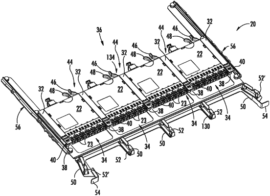
| CPC G02B 6/4452 (2013.01) [G02B 6/4453 (2013.01)] | 23 Claims |

|
1. A method of installing a fiber optic apparatus, comprising:
attaching a chassis to a fiber optic equipment rack, wherein the chassis supports a plurality of fiber optic equipment trays that are extendable relative to the chassis, wherein the plurality of fiber optic equipment trays are configured to support a plurality of fiber optic modules, and wherein each fiber optic module of the plurality of fiber optic modules comprises:
a main body having a front side, a rear side, opposed lateral walls, and an internal chamber,
a plurality of first fiber optic adapters disposed through the front side of the main body and configured to support a plurality of simplex fiber optic connectors or a plurality of duplex fiber optic connectors,
at least one second fiber optic adapter disposed through the rear side of the main body and configured to support at least one multifiber connector, and
a plurality of optical fibers disposed within the internal chamber and extending from the plurality of first fiber optic adapters to the at least one second fiber optic adapter;
extending a fiber optic equipment tray of the plurality of fiber optic equipment trays relative to the chassis;
installing at least two fiber optic modules of the plurality of fiber optic modules on the fiber optic equipment tray that is extended relative to the chassis, wherein for each of the at least two fiber optic modules:
the plurality of first fiber optic adapters are arranged in a row across the front side of the main body such that the row fits within a space that has a width W1 on the front side, and
the plurality of first fiber optic adapters provides a fiber optic connection density of at least one fiber optic connection per 7.0 millimeters (mm) of the width W1; and
pushing the fiber optic equipment tray back relative to the chassis after installing the at least two fiber optic modules.
|