| CPC G02B 6/125 (2013.01) [G02F 1/212 (2021.01); G02B 2006/12159 (2013.01)] | 10 Claims |

|
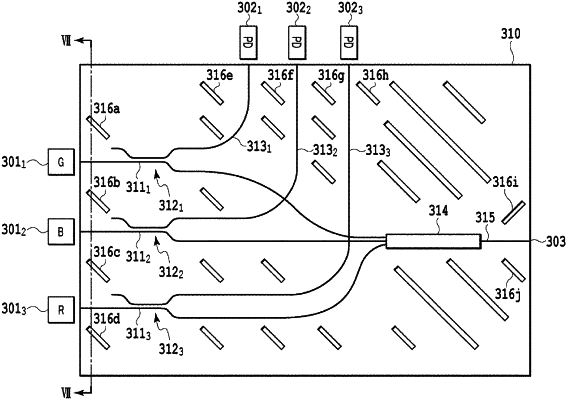
1. An optical beam combiner circuit comprising:
a plurality of branch portions configured to divide optical beams output from a plurality of input waveguides;
a combiner unit configured to combine optical beams, each of the optical beams being one of the divided optical beams obtained by one of the plurality of branch portions;
an output waveguide configured to output an optical beam obtained by the combiner unit combining the optical beams;
a plurality of monitoring waveguides configured to output optical beams, each of the optical beams being another of the divided optical beams obtained by one of the plurality of branch portions;
a plurality of light-blocking grooves provided on both sides with respect to each input waveguide, each of the plurality of light-blocking grooves being spaced apart by a predetermined interval from a corresponding one of the plurality of input waveguides, the plurality of light-blocking grooves being positioned to enable stray light not coupled to the plurality of input waveguides to be reflected toward an end surface different from an exit end surface of each monitoring waveguide and also different from an exit end surface of the output waveguide; and
a plurality of further light-blocking grooves provided around the combiner unit in parallel to the plurality of light-blocking grooves, the plurality of further light-blocking grooves having a different length than the plurality of light-blocking grooves,
wherein, because the further light-blocking grooves are in parallel to the plurality of light-blocking grooves, the further light-blocking grooves do not contact the plurality of light-blocking grooves.
|