| CPC G01R 31/2834 (2013.01) | 20 Claims |

|
1. A system, comprising:
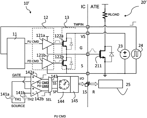
an electronic circuit, the electronic circuit comprising:
a first metal-oxide-semiconductor field-effect transistor (MOSFET) being a pull-up switch coupled to a voltage supply source,
a second MOSFET being a pull-down switch coupled to a lower potential node than the voltage supply source, the first MOSFET and the second MOSFET configured to supply a drive signal to a load, a source node of the first MOSFET being coupled to a drain node of the second MOSFET at a common terminal,
a first pre-driver circuit having an output node coupled to a control terminal of the first MOSFET, the first pre-driver circuit configured to receive a first command signal to drive the first pre-driver circuit, and
a second pre-driver circuit having an output node coupled to a control terminal of the second MOSFET, the second pre-driver circuit configured to receive a second command signal to drive the second pre-driver circuit;
a test circuit coupled to an automatic testing equipment to test the first and second pre-driver circuits, the test circuit comprising a test logic circuit configured to operate a built-in self-test sequence by generating the first command signal and the second command signal, based on a third command signal issued by the automatic testing equipment, the automatic testing equipment comprising a test load coupled to the common terminal;
a time measuring circuit coupled to the common terminal and configured to measure duration of signals at the common terminal in accordance with the first command signal and the second command signal during an execution of the built-in self-test sequence; and
a pass-fail check circuit coupled to the common terminal and configured to supply a drive signal to a load to satisfy a pass-fail condition.
|