| CPC G01R 27/2605 (2013.01) [B06B 1/0253 (2013.01); B06B 1/06 (2013.01); B06B 2201/72 (2013.01)] | 9 Claims |

|
1. A method for determining an electric capacitance Csw of an electromechanical oscillatory system (100), which comprises a piezoelectric element (10) and at least one additional element coupled, with respect to oscillation, to the piezoelectric element (10), the piezoelectric element (10) having an electrode and a counter electrode,
comprising the following steps:
a) applying an electrical alternating voltage between the electrode and the counter electrode for the duration of an excitation interval in order to induce mechanical oscillation of the oscillatory system or of a sub-system of the oscillatory system so that after the excitation interval has expired, the oscillatory system or the sub-system performs a free oscillation without excitation,
b) after the end of the excitation and during the free oscillation of the oscillatory system or of the sub-system without excitation: measuring a time curve of a voltage U (1) between the electrode and the counter electrode, and
c) determining the electric capacitance Csw from the time curve of the voltage U (1), which time curve was measured in step b),
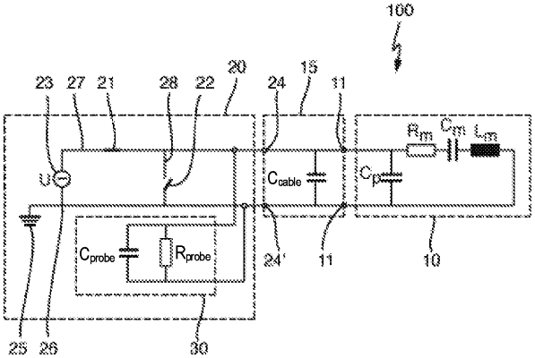
wherein, in step b), a measuring device (30) having an internal capacitance Cprobe and an internal resistance Rprobe is used to measure the time curve of the voltage (1), and wherein step c) comprises the following sub-steps:
aa) determining a time curve of a DC voltage portion UDC (2) from the time curve of the voltage U (1), which time curve was measured in step b),
bb) determining a characteristic time interval T, within which an initial value of the DC voltage portion UDC,O measured in step b) has fallen to the value UDC,O/e, wherein e is Euler's number,
cc) calculating the electric capacitance Csw with the characteristic time interval T.
|