| CPC G01N 21/455 (2013.01) [G01N 21/958 (2013.01); G02B 27/54 (2013.01)] | 14 Claims |

|
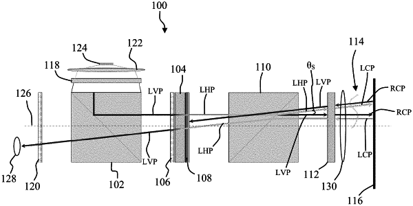
1. A digital projection focusing optical system for measuring a test object in a test section of an instrument, comprising:
a beam splitter configured to reflect an incident linear vertically polarized (LVP) light from a light source along an optical axis of the optical system;
an LCD element positioned to receive the LVP light from the beam splitter, wherein the LCD element comprises a selectable pixel element configured to:
generate a source grid comprising regions of the selectable pixel element switchable between a transparent state and an opaque state; and
rotate the LVP light by ninety degrees to be liner horizontally polarized (LHP) light when regions of the generated source grid are in the transparent state;
a polarizing prism configured to receive the LHP light from the LCD element and split the LHP light into two light beams, wherein:
a first light beam comprising LHP light is refracted by a small angle relative to the optical axis and exits the polarizing prism at that small angle; and
a second light beam comprising LVP light continues along and exits the polarizing prism aligned with the optical axis;
a quarter-wave plate positioned between the polarizing prism and a retroreflective background, wherein the quarter-wave plate is configured to:
modify the LVP light exiting the polarizing prism to right circularly polarized (RCP) light; and
modify the LHP light exiting the polarizing prism to left circularly polarized (LCP) light; and
an imaging lens positioned between the LCD element and the test section, wherein the imaging lens is configured to project the generated source grid onto the retroreflective background, wherein:
the retroreflective background is configured to:
reflect the incoming RCP light back towards the quarter wave plate and reverse the RCP light to LCP light;
reflect the incoming LCP light back towards the quarter wave plate and reverse the LCP light to RCP light; and
reflect an image of the projected source grid; and
the imaging lens projects the reflected image of the source grid back onto the LCD element.
|