| CPC G01L 1/2287 (2013.01) [B41M 3/006 (2013.01); B41M 5/0023 (2013.01)] | 13 Claims |

|
1. A method of manufacturing a flexible strain sensor, comprising:
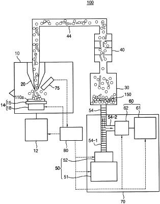
placing a flexible substrate on a movable stage in a working chamber in which the movable stage capable of a desired movement according to a control signal, and an nozzle capable of jetting toward an upper surface of the movable stage are installed therein, and with which a first pressure control unit capable of controlling an internal pressure of the working chamber is combined, and preparing a printing material mixture including metal nanoparticles and carbon nanotubes (CNTs) in a form of powder to be input into a printing material tank provided with an upper outlet communicating with a nozzle through a first communication pipe and a lower inlet to which a second pressure control unit capable of controlling pressure is combined;
controlling, by a control unit, a movement of the movable stage by providing a predetermined movement control signal to the movable stage to move the flexible substrate at a desired speed along a path corresponding to a predetermined conductive line pattern of a strain sensor;
forming a relatively low pressure atmosphere inside the working chamber by operating the first pressure control unit, and simultaneously a relatively high pressure atmosphere at a lower inlet of the printing material tank by operating the second pressure control unit;
in parallel with the controlling the movement of the movable stage, forcibly conveying the printing material mixture in an aerosolized state through the first communication pipe from the printing material tank, to be jetted out through the nozzle toward a surface of the flexible substrate by a compression wave caused by a pressure difference between the low pressure atmosphere and the high pressure atmosphere;
directly printing a predetermined conductive line pattern of the strain sensor on the flexible substrate through a process in which the printing material mixture jetted out through the nozzle collides with the surface of the flexible substrate to create cracks on the surface, and the CNTs penetrate into the cracks and are mechanically locked with the flexible substrate, and then following metal nanoparticles and CNTs of the printing material mixture are deposited to a predetermined width and height on the surface of the flexible substrate;
connecting first and second lead wires, which electrically extend to protrude out of the flexible substrate, to both ends of the predetermined conductive line pattern of the strain sensor; and
bonding a flexible cover having a same size as the flexible substrate to the surface of the flexible substrate on which the predetermined conductive line pattern is printed, so that the predetermined conductive line pattern is sandwiched between the flexible substrate and the flexible cover.
|