| CPC F16K 27/041 (2013.01) [F16K 11/07 (2013.01); F16K 31/5286 (2013.01); F16K 2200/3053 (2021.08)] | 10 Claims |

|
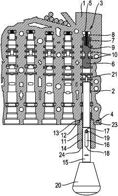
1. A mounting aid device (22) for mounting a valve slide (6) in a housing bore (2) of a valve housing (1) of a slide valve, wherein the valve slide (6) is force-loaded at a first end region of the valve slide (6) by a pretensioned spring element supported on the valve housing (1) and the second end region of the valve slide (6) is loadable by an actuating force against the force of the spring element, wherein the valve slide (6) is movable between a first end position and a second end position, axial movement of the valve slide (6) is limited when the spring element is compressed in the first end position of the valve slide (6), and movement travel of the valve slide (6) is limited when the spring element is not compressed in the second end position of the valve slide (6), and wherein the housing bore (2) on a side opposite the spring element opens coaxially to an exterior and is closable, the mounting aid device (22) comprising:
a guide piece (11);
a mounting slide (15) arranged movably in a guide (14) of the guide piece (11), the mounting slide (15) protruding out of the guide (14) of the guide piece (11) on both sides of the guide (14);
wherein the guide piece (11) comprises a first stop (17) and a second stop (18) with an elongated slot (16) extending axially between the first and second stops (17,18),
wherein the guide piece (11) comprises a third stop (13), the guide piece (11) with the guide (14) placeable coaxially to the housing bore (2) when the third stop (13) of the guide piece (11) contacts the valve housing (1),
wherein a stop pin (19) is connected to the guide piece (11), the stop pin (19) extending transversely to a longitudinal extension of the mounting slide (15) through the elongated slot (16) of the guide piece (11), the mounting slide (15) movable along an axial path delimited by translation of the stop pin (19) in the elongated slot (16) of the guide piece (11) between the first and second stops (17,18),
wherein the mounting slide (15) is extendable into the housing bore (2) in order to contact the second end region of the valve slide (6) when the third stop (13) of the guide piece (11) contacts the valve housing (1), and
wherein, by force-loading of the mounting slide (15) under compression of the spring element, the valve slide (6) is movable with the mounting slide (15) until the valve slide (6) reaches the first end position.
|