| CPC F16B 19/00 (2013.01) [B64D 25/14 (2013.01)] | 7 Claims |

|
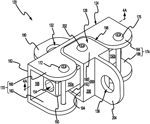
1. A releasable restraint, comprising:
a bracket;
a first pin extending between a first flange of the bracket and a second flange of the bracket;
a second pin extending between a third flange of the bracket and a fourth flange of the bracket;
a puller removably coupled to the bracket;
a first tube portion rotatably coupled to the puller;
a second tube portion rotatably coupled to the puller;
a torsion spring configured to bias the first tube portion toward the first pin and to bias the second tube portion toward the second pin; and
a third pin coupled to the puller;
wherein the first tube portion and the second tube portion are configured to rotate about the third pin;
wherein the torsion spring is configured to bias the first tube portion in a first circumferential direction about the third pin, and wherein the torsion spring is configured to bias the second tube portion in a second circumferential direction about the third pin, the second circumferential direction being opposite the first circumferential direction;
wherein the puller includes a first puller flange extending from an interior surface of the puller and a second puller flange extending from the interior surface of the puller, and wherein the third pin extends between the first puller flange and the second puller flange; and
wherein in a secured position, the first puller flange is located in a first groove defined by the first flange, the third flange, and an interior surface of the bracket, and wherein in the secured position, the second puller flange is located in a second groove defined by the second flange, the fourth flange, and the interior surface of the bracket.
|