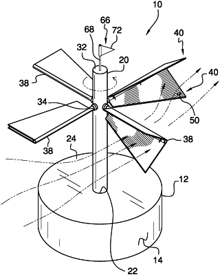
| CPC F03D 7/06 (2013.01) [F03D 9/25 (2016.05); F03D 15/00 (2016.05); H02K 7/183 (2013.01); F05B 2220/706 (2013.01); F05B 2240/211 (2013.01); F05B 2270/321 (2013.01)] | 7 Claims |

|
1. A vertical wind turbine assembly for converting wind energy into electrical energy, said assembly comprising:
a base being positioned on the ground in an area known to experience windy conditions;
a generator being positioned within said base;
a shaft being rotatably attached to said base, said shaft being mechanically coupled to said generator;
a plurality of couplings, each of said plurality of couplings being attached to an outer surface of said shaft, said plurality of couplings being evenly spaced apart from each other and being distributed around a full circumference of said outer surface, said plurality of couplings being positioned closer to an upper end of said shaft than an upper wall of said base, each of said couplings having a well extending into a distal end of said couplings;
a plurality of arms, each of said plurality of arms being attached to said shaft having said plurality of arms radiating outwardly from said shaft, each of said arms extends into said well in said distal end of a respective one of said couplings on said outer surface of said shaft;
a plurality of sets of blades, each of said sets of blades being pivotally attached to a respective one of said plurality of arms, each of said sets of blades being positionable in a deployed position having each of said sets of blades angling away from said respective arm in opposing directions from each other wherein each of said sets of blades on each of said plurality of arms is configured to capture wind for rotating said shaft thereby turning said generator, each of said sets of blades being positionable in a stored position having said sets of blades parallel to each other wherein each of said sets of blades is configured to inhibit capturing the wind, each of said sets of blades has a coupled edge, a free edge, a first lateral edge and a second lateral edge, said first lateral edge having a length being greater than a length of said second lateral edge, said coupled edge of each of said sets of blades being pivotally attached to an exterior surface of said respective arm having each of said sets of blades extending along a substantial length of said respective arm, said coupled edge of each of said sets of blades is positioned on opposing sides of said exterior surface of said respective arm from each other, said first lateral edge of each of said sets of blades is positioned adjacent to a respective one of said couplings, said second lateral edge of each of said sets of blades is positioned adjacent to a distal end of said respective arm;
a plurality of actuators, each of said plurality of actuators being coupled between a respective one of said plurality of arms and a respective one of said plurality of sets of blades, each of said plurality of actuators urging said respective sets of blades between said deployed position and said stored position; and
a wind direction sensor being integrated into said shaft wherein said wind direction sensor is configured to be exposed to wind, said wind direction sensor being rotated to indicate a direction of the wind, said wind direction sensor being in communication with each of said plurality of actuators, each of said plurality of actuators being actuated to urge said respective blades between said deployed position and said stored position depending on the direction of wind.
|