| CPC F02K 3/075 (2013.01) [F05D 2260/213 (2013.01)] | 9 Claims |

|
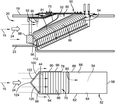
1. A bypass duct assembly for a gas turbine engine, the bypass duct assembly comprising:
a bypass duct arranged circumferentially around a central axis of the gas turbine engine and configured to direct bypass air through the bypass duct, the bypass duct including an outer wall defining an outer boundary of a flow path of the bypass air and an inner wall defining an inner boundary of the flow path of the bypass air,
a heat exchanger assembly arranged within the flow path and configured to transfer heat from a fluid passing through the heat exchanger assembly to a first portion of the bypass air while allowing a second portion of the bypass air to pass around the heat exchanger assembly, the heat exchanger assembly including a heat exchanger that conducts the fluid therethrough and a vane box arranged around the heat exchanger to direct the first portion of the bypass air into the heat exchanger, wherein the heat exchanger is coupled with the outer wall and extends radially inward from the outer wall toward the inner wall, and
an inlet cowl located upstream of the heat exchanger assembly to collect the first portion of the bypass air and direct the first portion of the bypass air into the heat exchanger assembly, the inlet cowl is coupled with the vane box and has a cowl duct that includes a first side wall that extends radially inward from the outer wall and a second side wall that extends radially inward from the outer wall and is spaced apart circumferentially from the first side wall.
|