|
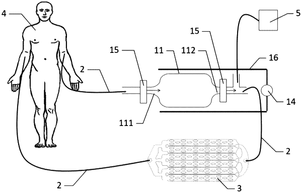
1. A fluid component capture system, comprising a fluid tube device, a circulating power apparatus device, and a component capture device, wherein the circulating power apparatus device and the component capture device are connected in series to a fluid circulating system via the fluid tube device to form an extracorporeal fluid circulating pathway, the fluid tube device further comprises a bypass tube connected in parallel with the component capture device, the bypass tube is provided with a flow-limiting valve configured to adjust the flow rate; the component capture device comprises a microfluidic chip or a chipset, the flow-limiting valve which is arranged in series or in parallel with the microfluidic chip, the microfluidic chip comprises a substrate layer and a cover sheet layer sequentially arranged from bottom to top, a component capture chamber is arranged between the substrate layer and the cover sheet layer, a fluid inlet and a fluid outlet communicating with the component capture chamber are arranged on the cover sheet layer, the component capture chamber is divided into a buffer zone and a lane portion, the lane portion is divided into two or more lanes arranged in parallel by setting a bypass flow block, and a pin-fin row array is arranged in the lane in a flow direction, the pin-fin rows are arranged in parallel in the lane at specific intervals of 0.5 to 1 diameter of pin-fin row.
|
