| CPC C01G 53/50 (2013.01) [H01M 4/131 (2013.01); H01M 4/1391 (2013.01); H01M 4/505 (2013.01); H01M 4/525 (2013.01); H01M 10/0525 (2013.01); C01P 2004/51 (2013.01); C01P 2004/62 (2013.01); C01P 2006/40 (2013.01)] | 10 Claims |

|
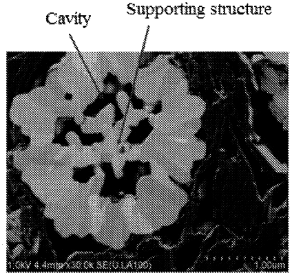
1. A positive electrode material having a multi-cavity structure, wherein the positive electrode material is formed by aggregation of a plurality of primary particles, and a part of the primary particles grow in an oriented manner to form supporting structures, the supporting structures overlapping each other inside the positive electrode material to form a plurality of cavities;
wherein a number of the plurality of cavities inside the positive electrode material is within a range of 3-12; and
wherein a composition of the positive electrode material is represented by formula (2):
Li1+aNi1−x−y−zCoxMnyMzO2, formula(2),
wherein −0.8≤a≤0.3, 0<x≤0.5, 0≤y≤0.5, and 0≤z≤0.1; and
wherein M is one or more selected from the group consisting of La, Cr, Mo, Ca, Fe, Hf, Ti, Zn, Y, Zr, W, Nb, Sm, V, Mg, B, Al, Sr, and Ba,
wherein the supporting structures have a thickness within a range of 70-800 nm, and the supporting structures have a length within a range of 100-1,500 nm;
wherein a change rate of K90 of the positive electrode material satisfies formula (3):
AK90=(K90′−K90)/K90×100%≤50%, formula (3);
wherein K90 and K90′ each denote the K90 particle size distribution of the positive electrode material before and after applying a pressure of 30 kN to the positive electrode material, respectively;
and/or,
an incremental amount of a particle size distribution proportion of the positive electrode material satisfies formula (4);
ΔD≤1=D≤1′−D≤1≤20%, formula (4);
wherein D≤1′ and D≤1 each denote the particle size distribution proportion of the positive electrode material with a particle size less than 1 μm before and after applying a pressure of 30 kN to the positive electrode material, respectively.
|