| CPC B64C 29/0033 (2013.01) [B64C 1/20 (2013.01); B64C 1/22 (2013.01); B64C 3/52 (2013.01); B64C 27/22 (2013.01); B64D 27/24 (2013.01); B64D 29/00 (2013.01); B64D 35/04 (2013.01); B64D 35/08 (2013.01); H02K 7/1861 (2013.01); B64D 27/026 (2024.01)] | 10 Claims |

|
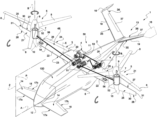
1. A convertiplane (1, 1′, 1″) comprising:
a fuselage (2) having a first longitudinal axis (A) and, in turn, comprising a nose (12) and a tail portion (13);
a pair of wings (3) arranged on respective opposite sides of said fuselage (2), carrying respective rotors (5) and generating a lift value; a pair of engines (4) of the thermal type and operatively connected to said rotors (5);
a pair of electric motors (52) operatively connected to respective said rotors (5) and adapted to drive the rotors (5) in rotation;
a pair of electric generators (51) electrically connected to respective said electric motors (52) and operatively connected to respective said engines (4); and
an interconnection shaft (11) interposed between said engines (4) and arranged in the said fuselage (2) for the greater parts of its width;
each said rotor (5), in turn, comprising a mast (9) rotatable about a second axis (B);
said mast (9) of each said rotor (5) being integrally tiltable with said second axis (B) about a relative third axis (E) transversal to said second axis (B) and with respect to said fuselage (2), so as to set said convertiplane (1, 1′, 1″) between a helicopter configuration and an aeroplane configuration;
each said second axis (B) being, in use, transversal to said first axis (A) of said convertiplane (1, 1′, 1″) in said helicopter configuration and being, in use, substantially parallel to said first axis (A) in said aeroplane configuration;
said engines (4) being interposed between said rotors (5) along a direction of extension of the relative said wing (3);
said engines (4) being arranged below and connected to a bottom surface (49) of the relative wing (3) with reference to a normal operating configuration of said convertiplane (1, 1′, 1″) set, in use, in said aeroplane configuration;
wherein said engines (4) are arranged at a connection interface between said fuselage (2) and the relative said wing (3);
each said engine (4) being arranged at a root portion of the relative said wing (3);
said engines (4) being positioned in respective interface corners between said fuselage (2) and respective said wings (3), and being connected to respective sides of said fuselage (2);
wherein each said wing (3), in turn, comprises:
a first portion (20), fixed with respect to said fuselage (2);
a second tip portion (21), integrally tiltable with the relative said mast (9) about the relative said third axis (E); and
a third intermediate portion (22), which is interposed between the respective said first portion (20) and the respective said tip portions (21);
said third intermediate portion (22) of each wing (3) being hinged to said first portion (20) of the respective wing (3) about a respective fourth axis (I).
|