| CPC B60L 58/12 (2019.02) [B60L 50/60 (2019.02); B60L 53/50 (2019.02); B60L 58/18 (2019.02); G01R 31/007 (2013.01); G01R 31/3648 (2013.01); H01M 10/44 (2013.01); H01M 10/48 (2013.01); H02J 7/0013 (2013.01); H02J 7/00712 (2020.01); H02J 7/342 (2020.01); H01M 2220/20 (2013.01)] | 18 Claims |

|
1. A battery control device comprising:
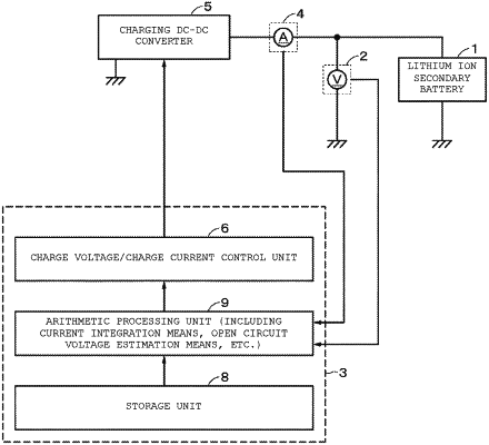
a charge/discharge controller configured to charge or discharge a secondary battery during diagnosis;
an open circuit voltage curve acquisition device configured to acquire an open circuit voltage by charging or discharging the secondary battery; and
an arithmetic processor configured to estimate a potential of a positive electrode and a potential of a negative electrode from an open circuit voltage curve,
wherein
a charge cut-off voltage to stop charging and a discharge cut-off voltage to stop discharging are changed such that an estimated potential of the positive electrode does not exceed an upper limit and a lower limit of potential that are preset,
as the number of cycles increases, the charge cut-off voltage is updated to be lower than the charge cut-off voltage at a first charging,
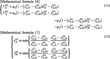
wherein the upper limit of the charge cut-off voltage is changed not to exceed the charge cut-off voltage Vfc that is shown in formula (11),
  wherein Qp is a positive net capacity or a positive electrode expansion rate, Qn is a negative net capacity or a negative electrode expansion rate, Sp is a positive slippage or a positive electrode parallel displacement, and Sn is a negative slippage or a negative electrode parallel displacement,
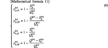
wherein a degree of charge of the positive electrode in the fully charged state is denoted as yp,fc, a degree of charge of the positive electrode in the fully discharged state as yp,fd, a degree of charge of the negative electrode in the fully charged state as yn,fc, a degree of charge of the negative electrode in the fully discharged state as yn,fd, values are expressed as in formula (6) using a positive net capacity, a negative net capacity, the positive slippage, the negative slippage, and a discharge capacity,
wherein a positive electrode potential function is denoted as φp (x), a negative electrode potential function is denoted as φn (x), x is a degree of charge, which takes a range of 0 to 1, the closer x is to 0, the more charged the battery is, and the closer x is to 1, the more discharged the battery is, and superscripts (n) on an upper right of y and Q represent the number of charge/discharge cycles, and
wherein the discharge cut-off voltage is set to Vfd, and superscript (n) on an upper right of V represents the number of charge/discharge cycles, and sfc and sfd in formula (11) are defined as in formula (12).
|