| CPC B60L 5/38 (2013.01) [B60L 5/08 (2013.01); B60L 5/30 (2013.01); B60L 5/36 (2013.01); B60L 5/39 (2013.01)] | 14 Claims |

|
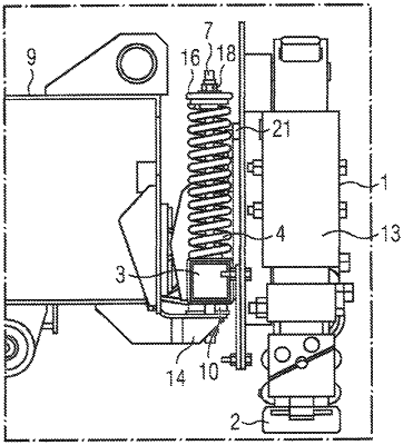
1. A current collector arrangement for a vehicle, which has an upward and downward deflectable current collector with a contact shoe for collecting current from a conductor rail, the current collector being connected to the vehicle in a sprung manner, the arrangement comprising:
a carrier arranged between the current collector and the vehicle, said carrier being connected to the vehicle via a first vertically extending spring and a second vertically extending spring as well as a joint;
wherein the first spring and the second spring each have at least one reserve spring-length region for extraordinary deflections of the current collector;
wherein absolute values of extraordinary deflections exceed absolute values of ordinary deflections of the current collector.
|