| CPC B60K 1/04 (2013.01) [B60K 11/04 (2013.01); B60L 1/00 (2013.01); B60L 50/60 (2019.02); B62D 25/084 (2013.01); B62D 25/10 (2013.01); B60K 2001/003 (2013.01); B60K 2001/0411 (2013.01); B60L 2200/40 (2013.01); B62D 49/06 (2013.01)] | 7 Claims |

|
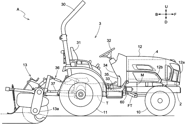
1. An electric work vehicle, comprising:
a travel battery;
an auxiliary battery to supply electric power to only one or more auxiliaries;
a motor drivable on electric power supplied by the travel battery;
a travel device drivable by only the motor;
a voltage converter positioned forward of the travel battery to step down a voltage of direct-current electric power from the travel battery and supply the direct-current electric power to the auxiliary battery; and
a radiator positioned forward of the travel battery; wherein
the electric power that the auxiliary battery supplies is not used to drive the travel device; and
the voltage converter and the radiator are laterally next to each other in a plan view.
|