| CPC B29C 51/28 (2013.01) [B29C 51/004 (2013.01); B29C 51/087 (2013.01); B29C 51/20 (2013.01); B29C 70/462 (2013.01); B29K 2821/00 (2013.01); B29K 2995/0082 (2013.01); B29L 2031/003 (2013.01); B29L 2031/3082 (2013.01)] | 20 Claims |

|
1. A method of forming a contoured composite hat stringer having a contoured hat section including sides and a cap, comprising:
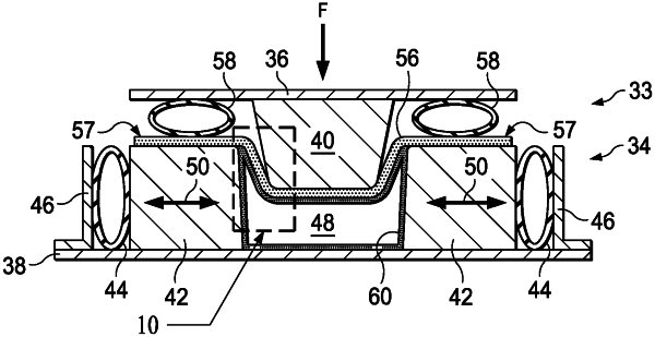
placing a composite charge on a pair of dies mounted to a flexible bottom plate, the pair of dies forming a die cavity;
installing an inflatable bladder within the die cavity, the inflatable bladder resting on the flexible bottom plate;
inflating the inflatable bladder to completely fill the die cavity;
forcing the composite charge into the die cavity with a punch mounted to a flexible top plate, the punch in contact with a first side of the composite charge;
constraining the cap between the inflated bladder and the punch as the composite charge is being forced into the die cavity, the inflated bladder in contact with the cap from a second side of the composite charge; and
applying pressure to outer edges of the composite charge with a pair of inflatable flange pinch bladders, the pair of inflatable flange pinch bladders positioned between the outer edges of the composite charge and the flexible top plate and in contact with the first side of the composite charge, wherein the applying pressure includes allowing the outer edges of the composite charge to slip over the pair of dies during the forcing the composite charge into the die cavity.
|