| CPC B24B 41/067 (2013.01) [B24B 19/226 (2013.01); B24B 27/0023 (2013.01); B24B 37/27 (2013.01); G02B 6/36 (2013.01); B24B 37/34 (2013.01); G02B 6/3863 (2013.01); G02B 6/3866 (2013.01)] | 10 Claims |

|
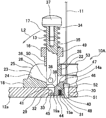
1. A placing member configured to be installed on a base of an optical fiber ferrule polishing jig used for polishing optical fiber ferrules, the placing member comprises:
a raised portion located on the base;
pivoting rods installed so as to be capable of being rotated;
a plurality of slide locks; and
a plurality of coil springs, each of the plurality of coil springs is disposed around a respective pivoting rod of the pivoting rods, and is configured to bias a respective slide lock of the plurality of slide locks toward a bottom end of each respective pivoting rod, wherein
the raised portion comprises:
first support portions, each of the first support portions respectively supporting each of the pivoting rods in a state of being rotated inward in a radial direction of the placing member;
pivot-openings, each of the pivot-openings respectively communicating with each of the first support portions;
second support portions, each of the second support portions respectively communicating with each of the pivot-openings for respectively supporting each of the pivoting rods in a state of being rotated outward in the radial direction of the placing member; and
a plurality of lock holes formed in the raised portion, wherein
each of the first support portions includes an upper opening which is open toward an upper side of the raised portion,
each of the second support portions includes a side opening which is open outward in the radial direction,
each of the plurality of slide locks is disposed around each respective pivoting rod and is slidable along an axial direction of each respective pivoting rod,
each of the plurality of slide locks has a lower end portion configured to enter a respective lock hole of the plurality of lock holes,
in the state of being rotated inward in the radial direction, each of the pivoting rods is located in each upper opening and is supported by an inner wall of the respective upper opening,
in the state of being rotated outward in the radial direction, each of the pivoting rods is located in each side opening and supported by an inner wall of the respective side opening, and
each of the pivoting rods is configured to be rotated between each respective upper opening and side opening.
|