| CPC B21C 37/16 (2013.01) | 12 Claims |

|
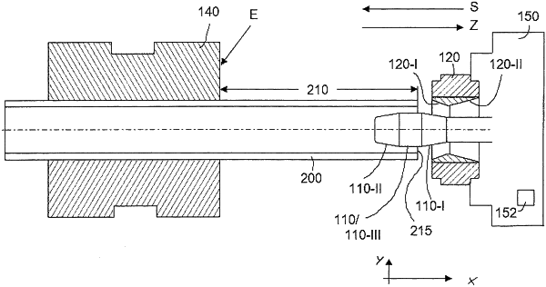
1. A method for axially shaping a tube (200) with a mandrel (110) guided in the tube (200) and an annular die (120) guided on an outside of the tube (200), an inside diameter of the annular die (120) being smaller than an original outside diameter of the tube (200),
wherein the annular die (120) has at least one conical transition portion (120-I, 120-II) that extends axially inside the annular die (120),
wherein the mandrel (110) has at least one conical transition portion (110-I, 110-II) that extends axially on an outside of the mandrel (110), and
wherein the annular die and the mandrel in their juxtaposition span an annular gap (130) for passing through and shaping a wall of the tube (200),
the method comprising:
clamping the tube (200) with an original wall thickness in a clamping device (140) such that at least one free portion (210) of the tube (200) remains for shaping the tube (200);
inserting the mandrel (110) into the tube (200);
reducing the original outside diameter of the tube (200) by pushing the annular die (120) in a pushing direction (S) towards the clamping device (140) over the free portion (210) of the tube (200), wherein the mandrel (110) leads the annular die (120) in the pushing direction;
upon reaching an end position (E), reversing the direction of movement of the annular die (120) and the mandrel (110) from the pushing direction (S) to an opposite pulling direction (Z);
moving, in a first setting step, the annular die (120) and mandrel (110) in relation to one another to a first preset annular-gap setting; and
moving, in a first shaping step, the annular die (120) and mandrel (110) in the pulling direction (Z) over a first partial portion (T1) of the free tube portion (210), while maintaining the first preset annular-gap setting,
moving, in a subsequent second setting step, the annular die (120) and mandrel (110) in relation to one another to a negative annular-gap setting, in which the conical transition portions (110-I, 120-I) of the annular die (120) and the mandrel (110) taper towards a free end of the tube (200) and span the annular gap; and
moving, in a second shaping step, the annular die (120) and mandrel (110) in the pulling direction (Z) over a second partial portion (T2) of the free tube portion (210), while maintaining the second preset annular-gap setting, thereby causing an outer diameter of the tube in the second partial portion (T2) to be greater than an outer diameter of the tube in the first partial portion (T1).
|