US 12,070,758 B2
Centrifuge system with a measurement region of a diverter fluid circuit
Brian Ligertwood, Houston, TX (US); Daniele Marozzi, Berra Ferrara (IT); Colin Stewart, Houston, TX (US); Richard Bingham, Katy, TX (US); Bojan Mitric, Houston, TX (US); and Luciano Guandalini, Occhiobello Rovigo (IT)
Assigned to SCHLUMBERGER TECHNOLOGY CORPORATION, Sugar Land, TX (US); and MANTOVANI & VICENTINI S.R.L., Berra Ferrara (IT)
Appl. No. 15/733,615
Filed by M-I L.L.C., Houston, TX (US); and Mantovani & Vicentini S.R.L., Berra Ferrara (IT)
PCT Filed Mar. 27, 2019, PCT No. PCT/US2019/024169
§ 371(c)(1), (2) Date Sep. 16, 2020,
PCT Pub. No. WO2019/191155, PCT Pub. Date Oct. 3, 2019.
Claims priority of provisional application 62/648,392, filed on Mar. 27, 2018.
Prior Publication US 2021/0008572 A1, Jan. 14, 2021
Int. Cl. B04B 11/02 (2006.01); B04B 13/00 (2006.01); B04B 15/06 (2006.01); E21B 21/06 (2006.01)
CPC B04B 11/02 (2013.01) [B04B 13/00 (2013.01); B04B 15/06 (2013.01); E21B 21/065 (2013.01)] 14 Claims
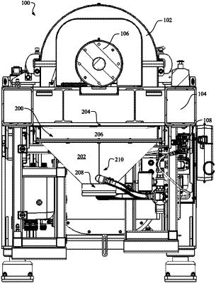
OG exemplary drawing
 
1. An apparatus, comprising:
a centrifuge bowl rotatable about its longitudinal axis;
a discharge unit positioned to receive discharge fluid from the centrifuge bowl, the discharge unit comprising a first outlet and a second outlet;
a diverter fluid circuit comprising a measurement region comprising a narrower diameter than a cross section of the discharge unit, wherein the diverter fluid circuit is coupled to the first outlet and a first portion of the discharge fluid flows through the first outlet to the measurement region, and wherein a second portion of the discharge fluid flows out of the discharge unit through the second outlet.