| CPC A61B 17/0469 (2013.01) [A61B 17/0482 (2013.01); A61B 17/0625 (2013.01); A61B 2017/00243 (2013.01); A61B 2017/00314 (2013.01); A61B 2017/00323 (2013.01); A61B 2017/0472 (2013.01)] | 12 Claims |

|
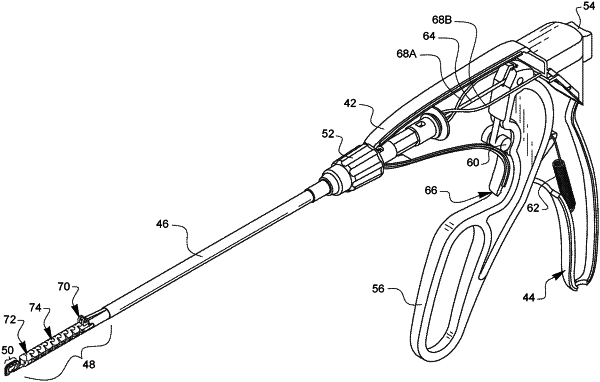
1. A minimally invasive surgical device, comprising:
a housing;
an actuator coupled to a first portion of the housing;
a shaft coupled to a second portion of the housing, the shaft extending from a proximal end to a distal end about a shaft axis, and wherein one or more interior surfaces of the shaft defines a shaft interior portion, and wherein a shaft mating feature is disposed at the distal end of the shaft;
a needle coupled to the actuator such that the needle is displaceable from a first position to a second position, wherein the needle comprises a needle tip at a distal end of the needle, and wherein at least a portion of the needle is disposed within the shaft interior portion;
an elongated flexible span extending from a proximal end to a distal end about a span axis, wherein the proximal end of the flexible span is disposed at or adjacent to the distal end of the shaft, the flexible span comprising:
an angling link disposed at the proximal end of the flexible span, the angling link comprising:
an angling link body;
a first angling link mating feature disposed at a proximal end of the angling link body and extending along a first pivot axis; and
a second angling link mating feature disposed at a distal end of the angling link body and extending along a second pivot axis that is normal to the first pivot axis;
a plurality of bending links, wherein each of the plurality of bending links comprises:
a bending link body;
a first bending link mating feature disposed at a proximal end of the bending link body; and
a second bending link mating feature disposed at a distal end of the bending link body, wherein each of the plurality of bending links includes only one first bending link mating feature and only one second bending link mating feature; and
an end link disposed at the distal end of the flexible span, the end link comprising:
an end link body; and
a first end link mating feature disposed at a proximal end of the end link body and extending along a third pivot axis that is parallel to the second pivot axis,
wherein the first angling link mating feature of the angling link engages the shaft mating feature such that the flexible span rotates relative to the distal end of the shaft about the first pivot axis,
wherein the plurality of bending links are aligned such a first of the plurality of bending links is disposed adjacent to the distal end of the angling link body and a second of the plurality of bending links is disposed adjacent to the proximal end of the end link body,
wherein the first bending link mating feature of the first of the plurality of bending links engages the second angling link mating feature of the angling link such that the first of the plurality of bending links rotates relative to the angling link about the second pivot axis that is normal to the first pivot axis,
wherein the second bending link mating feature of the second of the plurality of bending links engages the first end link mating feature of the end link such that the second of the plurality of bending links rotates relative to the end link about the third pivot axis that is parallel to the second pivot axis,
and wherein the first bending link mating feature of each of the plurality of bending links between the first of the plurality of bending links and the second of the plurality of bending links engages the second bending link mating feature of an adjacent one of the bending links between the first of the plurality of bending links and the second of the plurality of bending links such that each of the plurality of bending links is pivotable relative to the adjacent one of the bending links about a pivot axis that is parallel to the second pivot axis and the third pivot axis,
and wherein the first bending link mating feature of each of the plurality of bending links between the first of the plurality of bending links and the second of the plurality of bending links is one of a cylindrical or partially-cylindrical protrusion or a cylindrical or partially-cylindrical socket, and the second bending link mating feature of the adjacent one of the bending links is the other of the cylindrical or partially-cylindrical protrusion or the cylindrical or partially-cylindrical socket such that the cylindrical or partially-cylindrical protrusion is received into the cylindrical or partially-cylindrical socket such that the cylindrical or partially-cylindrical protrusion rotates within the cylindrical or partially-cylindrical socket; and
a distal tip coupled to the end link of the flexible span, wherein a notch in the distal tip defines a tissue bite area configured to receive a portion of tissue, wherein when the needle is in the first position, the needle tip of the needle is disposed at a proximal portion of the tissue bite area and when the needle is in the second position, the needle tip of the needle is disposed at a distal portion of the tissue bite area such that the needle tip of the needle extends through the portion of tissue disposed in the tissue bite area.
|