| CPC H02P 21/22 (2016.02) [H02P 27/12 (2013.01); B60R 16/03 (2013.01); H02P 2207/05 (2013.01)] | 11 Claims |

|
1. A method for operating a permanent magnet synchronous motor, the method comprising the following steps:
setting a maximum power;
determining a current vector in the dq coordinate system on the basis of one of a torque requirement and a power limitation and a torque requirement;
determining an output voltage vector in the dq coordinate system;
calculating a setpoint amount for a setpoint voltage vector on the basis of the maximum power, the current vector and the output voltage vector;
generating the setpoint voltage vector with the setpoint amount;
operating the permanent magnet synchronous motor at least with the setpoint voltage vector;
calculating the setpoint amount as the product of the factor ⅔ with a quotient comprising a dividend and a divisor;
calculating the dividend as the product of the maximum power and the amount of the output voltage vector; and
calculating the divisor as the sum of the product of the d components of the output voltage vector and the current vector on the one hand and the product of the q components of the output voltage vector and the current vector on the other hand.
|
|
5. An electronic control device with instructions comprising:
setting a maximum power;
determining a current vector in the dq coordinate system on the basis of one of a torque requirement and a power limitation and a torque requirement;
determining an output voltage vector in the dq coordinate system;
calculating a setpoint amount for a setpoint voltage vector on the basis of the maximum power, the current vector and the output voltage vector;
generating the setpoint voltage vector with the setpoint amount;
operating the permanent magnet synchronous motor at least with the setpoint voltage vector;
calculating the setpoint amount as the product of the factor ⅔ with a quotient comprising a dividend and a divisor;
calculating the dividend as the product of the maximum power and the amount of the output voltage vector; and
calculating the divisor as the sum of the product of the d components of the output voltage vector and the current vector and the product of the q components of the output voltage vector and the current vector.
|
|
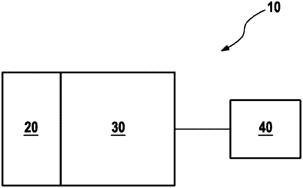
8. A motor arrangement comprising:
a permanent magnet synchronous motor,
an inverter for controlling the permanent magnet synchronous motor; and
an electronic control device for controlling the inverter by setting a maximum power;
determining a current vector in the dq coordinate system on the basis of one of a torque requirement and a power limitation and a torque requirement;
determining an output voltage vector in the dq coordinate system;
calculating a setpoint amount for a setpoint voltage vector on the basis of the maximum power, the current vector and the output voltage vector;
generating the setpoint voltage vector with the setpoint amount;
operating the permanent magnet synchronous motor at least with the setpoint voltage vector;
calculating the setpoint amount as the product of the factor ⅔ with a quotient comprising a dividend and a divisor;
calculating the dividend as the product of the maximum power and the amount of the output voltage vector; and
calculating the divisor as the sum of the product of the d components of the output voltage vector and the current vector and the product of the q components of the output voltage vector and the current vector.
|