| CPC H02M 7/217 (2013.01) [H02M 1/4258 (2013.01)] | 16 Claims |

|
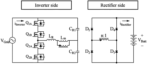
1. An alternating current (AC)-to-direct current (DC) (AC-DC) converter circuit system comprising:
an AC-DC converter configured to receive an AC input from an electric power source and convert the AC input into DC power,
wherein the AC-DC converter comprises:
a primary side that receives the AC input, the primary side comprising a plurality of field-effect transistors (FETs) that maintain a positive portion of the AC input to remain positive and switch a negative portion of the AC input to be positive to produce a positive AC waveform; and
a secondary side configured to allow the DC power to be output from the positive AC waveform of the primary side,
wherein the plurality of FETs of the primary side comprises a first pair of bidirectional switches, and on or off of each of the bidirectional switches is determined based on an AC waveform of the AC input, and
wherein each of the plurality of FETs comprises the first pair of bidirectional switches comprising a first bidirectional switch (Q1A) and a second bidirectional switch (Q1B) and a second pair of bidirectional switches comprising a third bidirectional switch (Q2A) and a fourth bidirectional switch (Q2B), and
when the AC input is received as a positive input, the first pair of bidirectional switches (Q1B and Q1A) are turned on/off at a same time ratio, the fourth bidirectional switch (Q2B) is turned on/off complementarily to the time ratio of the bidirectional switches (Q1B and Q1A), and the third bidirectional switch (Q2A) is maintained to be turned on, and
when the AC input is received as a negative input, the bidirectional switches (Q2B and Q2A) are turned on/off at a same time ratio, the first bidirectional switch (Q1A) is turned on/off complementarily to the time ratio of the bidirectional switches (Q2B and Q2A), and the second bidirectional switch (Q1B) is maintained to be turned on.
|