| CPC H02M 3/33573 (2021.05) [H02M 1/0058 (2021.05); H02M 3/33515 (2013.01); H02M 3/33584 (2013.01)] | 8 Claims |

|
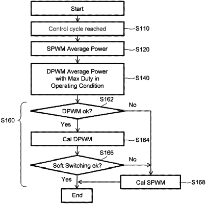
1. A method for determining an algorithm of converting power at every control cycle for converting power, and converting the power under the determined algorithm, comprising steps of:
calculating average power of an inductor on an input of a transformer upon power conversion under a Single PWM (SPWM) algorithm at the control cycle;
calculating average power of the inductor on the input of the transformer upon power conversion under a Dual PWM (DPWM) algorithm at the control cycle; and
converting the power under either of the algorithms of which the calculated average power of the inductor on the input of the transformer is greater,
wherein the DPWM algorithm drives a primary-side voltage of the transformer in a square wave to which a primary duty phase is applied, and drives a secondary-side voltage of the transformer in a square wave to which a secondary duty phase is applied,
wherein, upon step-up, the SPWM algorithm drives the secondary-side voltage of the transformer in the square wave, and drives the primary-side voltage of the transformer in the square wave to which a duty phase is applied,
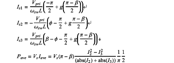
wherein, upon step-up, at the step of calculating the average power of the inductor on the input of the transformer upon power conversion under the SPWM algorithm at the control cycle, the average power is obtained under following equation:
 (Vpri: Primary-side voltage, Vsec=Vs: Secondary-side voltage
Ø: Phase difference between the primary-side voltage and the secondary-side voltage
α: Duty phase of the primary-side voltage, β: Duty phase of the secondary-side voltage
ωsw: Angular velocity at a switching frequency of a switching element
g: Input-output voltage ratio on the primary and secondary sides
Is1=I1, Is2=I2, Is3=I3
Pave: Average power
I1: Current value of the inductor at rising time θ0 of a primary-side voltage waveform without any duty
I2: Current value of the inductor at rising time θ1 after a duty of a secondary-side voltage waveform
I3: Current value of the inductor at falling time θ2 of the secondary-side voltage waveform
L: Inductance
Iave: Average current,
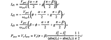
wherein, upon step-up, at the step of calculating the average power of the inductor on the input of the transformer upon power conversion under the DPWM algorithm at the control cycle, the average power is obtained under following equation:
 Vpri: Primary-side voltage, Vsec=Vs: Secondary-side voltage
Ø: Phase difference between the primary-side voltage and the secondary-side voltage
α: Duty phase of the primary-side voltage, β: Duty phase of the secondary-side voltage
ωsw: Angular velocity at a switching frequency of a switching element
g: Input-output voltage ratio on the primary and secondary sides
Id1=I1, Id2=I2 Id3=I3
Pave: Average power
I1: Current value of the inductor at rising time θ0 before a duty of the primary-side voltage waveform
I2: Current value of the inductor at rising time θ2 after a duty of the secondary-side voltage waveform
I3: Current value of the inductor at falling time θ3 of the secondary-side voltage waveform
L: Inductance
Iave: Average current.
|