| CPC H02M 3/158 (2013.01) [H02J 7/02 (2013.01); H02M 1/007 (2021.05); H02M 3/07 (2013.01); H02J 2207/20 (2020.01); H02M 3/073 (2013.01)] | 15 Claims |

|
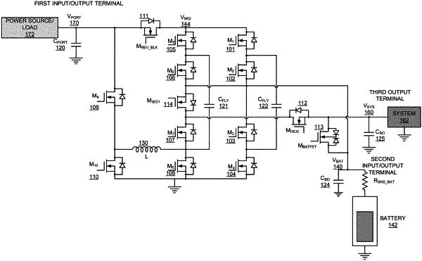
1. A hybrid power converter facilitating bidirectional power conversion, comprising: an input terminal comprising one or more capacitors, and is connected to an input power supply; one or more output terminals, each of the one or more output terminals connected to one or more output capacitors and an output load; a first converter network with interleaved phases, the first converter network comprising at least eight switches, wherein a first switch and a fifth switch are connected on a fourth terminal electrically coupled to a first input/output terminal through a reverse-blocking switch for blocking current, when required, from a second input/output terminal connected to battery as power source towards the first input/output terminal connected to a load, wherein a first set of parallel flying capacitors are connected across a shared node of the first switch and a second switch and a shared node of a third switch and a fourth switch, wherein a second set of parallel flying capacitors are connected across a shared node of the fifth switch and a sixth switch and a shared node of a seventh switch and an eighth switch, and wherein a shared node of the second switch and the third switch and a shared node of the sixth switch and the seventh switch are connected to a second input/output terminal connected to the battery;
a second converter network comprising at least four switches, wherein a series combination of a ninth switch and a tenth switch are connected from the first input/output terminal to a ground, and a shared node of the ninth switch and the tenth switch is connected via an inductor to a shared node of the seventh switch and the eighth switch, wherein the second set of parallel flying capacitors are connected to the inductor at the shared node of the seventh switch and the eighth switch,
wherein the second converter network comprises of four sub-networks, a fourth converter network, a fifth converter network, a sixth converter network and a seventh converter network, wherein reconfiguring any or a combination of the first converter network and the second converter network by switching or turning on plurality of switches facilitates a plurality of power converter networks.
|