| CPC H01R 13/533 (2013.01) [G01K 17/006 (2013.01); H01P 3/026 (2013.01); H01P 3/08 (2013.01); H01R 13/6683 (2013.01); H01R 24/52 (2013.01); H01R 2103/00 (2013.01)] | 19 Claims |

|
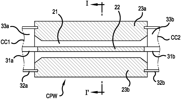
1. An adiabatic coaxial cable connector, comprising:
a chassis comprising a hollow cylindrical body;
a planar transmission line having first and second ends disposed in the hollow cylindrical body of the chassis;
a first coaxial-to-planar transition within the chassis and connected to the first end of the planar transmission line; and
a second coaxial-to-planar transition within the chassis and connected to the second end of the planar transmission line, wherein a ground plane of the planar transmission line is connected between tubular conducting shields of opposing coaxial cable ends.
|