| CPC G09G 3/20 (2013.01) [G09G 2320/0626 (2013.01); G09G 2360/16 (2013.01)] | 16 Claims |

|
1. An image pixel luminance adaptation apparatus comprising:
a connection to a video decoder,
wherein the video decoder is arranged to receive an encoded high dynamic range image and a metadata,
wherein the high dynamic range image is encoded according to a first maximum codeable luminance,
wherein the metadata specifies a first luma mapping function,
wherein the first luma mapping function specifies the offsets of luminances of pixels of a secondary image relative to the luminances of pixels of the encoded high dynamic range image for collocated pixel positions,
wherein the secondary image has a second maximum codeable luminance,
wherein the video decoder is arranged to output a decoded high dynamic range image and the first luma mapping function;
a display adaptation circuit,
wherein the display adaptation circuit is arranged to receive a value of a display maximum luminance,
wherein the value of a display maximum luminance specifies a maximum luminance that a connected display can display;
wherein the display adaptation circuit is arranged to receive an input luma mapping function,
wherein the display adaptation circuit is arranged to apply an algorithm,
wherein the algorithm calculates a display adapted luma mapping function based on the input luma mapping function and the display maximum luminance,
wherein the adapted luma mapping function corresponds in shape to the input luma mapping function but lies closer to a 45 degree increasing diagonal of a graph of the input luma mapping function in perceptually uniformized axes than the input luma mapping function,
wherein the shape correspondence is such that a ratio of orthogonal distances to the diagonal of two points lying on the curve of the input luma mapping function equals a ratio of orthogonal distances of two points of the adapted luma mapping function,
wherein two points of the adapted luma mapping function lie on the same two orthogonal projections;
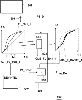
an alternative luma mapping function determination circuit,
wherein the alternative luma mapping function circuit is arranged to determine an alternative luma mapping function,
wherein the display adaptation circuit comprises a combination circuit,
wherein the combination circuit is arranged to combine the first luma mapping function and the alternative luma mapping function into a combined luma mapping function,
wherein the display adaptation circuit is arranged to use the combined luma mapping function to yield an adapted combined luma mapping function; and
a luma mapping circuit, wherein the luma mapping circuit is arranged to receive pixel lumas of the decoded high dynamic range image,
wherein the luma mapping circuit is arranged to apply the adapted combined luma mapping function to the received pixel lumas so as to obtain output lumas of an output image.
|