| CPC G01N 33/491 (2013.01) [B01L 3/502761 (2013.01); G01N 15/1459 (2013.01); G01N 15/1484 (2013.01); G01N 33/4915 (2013.01); B01L 2200/0668 (2013.01); B01L 2300/087 (2013.01); B01L 2300/0809 (2013.01); G01N 2015/149 (2013.01)] | 8 Claims |

|
1. A particle separating and measuring device comprising:
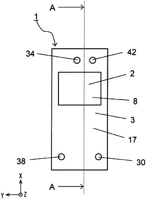
a first flow path device having a plate-like shape and including a pre-separation flow inlet through which a fluid flows in that contains specific particles to be separated, a main flow path connected to the pre-separation flow inlet, a plurality of branch flow paths each connected to the main flow path, and a post-separation flow outlet through which a first fluid flows out that contains the specific particles that have been separated; and
a second flow path device having a plate-like shape and having a first region on which the first flow path device is placed, and a second region that serves as a measurement region for the specific particles, the second flow path device including a first flow inlet through which the first fluid flows in, a second flow inlet through which a second fluid not containing the specific particles flows in, a first flow path connected to the first flow inlet and through which the first fluid passes, and a second flow path connected to the second flow inlet and through which the second fluid passes, wherein the first flow path and the second flow path are arranged in the second region;
wherein the post-separation flow outlet is arranged in a lower surface of the first flow path device, and is placed on the second flow path device to face and connect to the first flow inlet that is arranged in an upper surface of the first region of the second flow path device, and
a size of an opening of the first flow inlet is larger than a size of an opening of the post-separation flow outlet.
|