| CPC G01B 11/2408 (2013.01) [G01B 11/002 (2013.01); G01B 11/26 (2013.01)] | 20 Claims |

|
1. An inner surface shape measurement device, comprising:
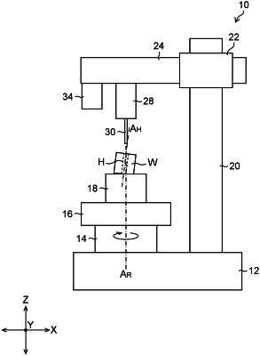
a rotating body configured to rotate around a rotation axis parallel to a first direction;
a linear-and-tilting-motion stage supported by the rotating body, the linear-and-tilting-motion stage being capable of changing a position thereof and a tilt thereof, the position being a position in a flat surface with respect to the rotating body, the tilt being a tilt with respect to the flat surface, the flat surface being orthogonal to the first direction;
a displacement detector configured to detect displacement of an inner side surface of a hole of a workpiece, using a probe capable of being moved in the first direction by a first linear-motion mechanism, the workpiece being fixed to the linear-and-tilting-motion stage and rotating together with the rotating body, the probe being a contact probe or a non-contact probe each extending parallel to the first direction;
a camera having an optical axis parallel to the first direction;
an observation controller configured to observe, using the camera: a first position and a second position of the hole of the workpiece at a first rotation angle of the rotating body; and the first position and the second position of the hole of the workpiece at a second rotation angle of the rotating body, the second position being a position different from the first position in the first direction, the second rotation angle being an angle different from the first rotation angle;
a position-and-tilt calculator configured to calculate a position and a tilt of the hole from coordinates of the observed first position and the observed second position of the hole at the first rotation angle of the rotating body, and from coordinates of the observed first position and the observed second position of the hole at the second rotation angle of the rotating body; and
an output unit configured to output hole information including the calculated position and tilt of the hole.
|