| CPC F16J 15/3404 (2013.01) [F16J 15/34 (2013.01); F16J 15/3452 (2013.01); F16J 15/3464 (2013.01); F04D 29/122 (2013.01); F05B 2240/57 (2013.01)] | 3 Claims |
|
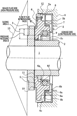
1. A mechanical seal comprising:
a pair of seal rings sliding relatively to each other, a first one of the pair of seal rings being a stationary-side seal ring provided at a housing via a cartridge in a non-rotating state and in an axially movable state, a second one of the pair of seal rings being a rotating-side seal ring fixed to a rotating shaft, the seal rings having respective sliding faces extending radially for sealing sealed fluid against leakage;
wherein the cartridge has an outer cylindrical portion fitted into an inner periphery of the housing, a disk portion extending radially inward from one end of the outer cylindrical portion at an opposite side of the sliding face of the stationary-side seal ring, and an inner cylindrical portion extending from a radially inner portion of the disk portion in an axial direction;
a spring provided between the stationary-side seal ring and the disk portion of the cartridge and configured for pressing the stationary-side seal ring against the sliding face of the rotating-side seal ring; and
a spring holder provided between the stationary-side seal ring and the spring,
wherein the stationary-side seal ring has a step portion radially outward on the opposite side of the sliding face, wherein the step portion is a recess with a substantially L-shaped cross section and is provided with an axial peripheral surface and a radial surface,
wherein the spring holder has a substantially L-shaped cross section and is provided with a cylindrical portion and a disk portion,
the cylindrical portion is disposed along the axial peripheral surface,
the disk portion is disposed on the radial surface,
wherein dynamic pressure generation grooves are provided on the sliding face of the rotating-side seal ring, communicate with a circumferential edge on an inner peripheral side of the sliding face and do not communicate with a circumferential edge on an outer peripheral side of the sliding face,
at least one fluid introduction groove is provided on the outer peripheral side of the sliding face, and
the at least one fluid introduction groove has an opening that is open only to the circumferential edge on the outer peripheral side of the sliding face and has a shape largest at the opening and tapered radially inward, and
the at least one fluid introduction groove is radially inclined such that:
a tapered portion of the at least one fluid introduction groove is located upstream at a time of rotation; and
the opening of the at least one fluid introduction groove is located downstream at the time of rotation,
wherein a rotation prevention portion for the stationary-side seal ring is provided within the outer most portion of the cartridge which is fitted into the inner periphery of the housing in the axial direction:
the outer peripheral portion of the stationary-side seal ring being provided with a cutout groove, and the axial width of the rotation prevention portion is set sufficiently longer than the axial width of the cutout groove of the stationary-side ring, so that the rotation prevention portion is able to contact entirely the axial width of the cutout groove of the stationary-side ring,
and the rotation prevention portion being movable relative to the cutout groove in the radial direction and also the axial direction, and the rotation prevention portion preventing for the rotation of the stationary-side seal ring in the peripheral direction by engaged to the cutout groove,
wherein the rotation prevention portion is formed of a material having a higher wear resistance than a material of the stationary-side seal ring and has an axial width set such that even when the stationary-side seal ring axially moves, the outer peripheral portion of the stationary-side seal ring is located inside opposite ends of the rotation prevention portion, and
wherein the sliding face of the stationary-side seal ring has an inner diameter set smaller than a diameter of an inner cylindrical portion of the cartridge.
|