| CPC F02K 1/1223 (2013.01) [F02K 1/822 (2013.01); F05D 2220/323 (2013.01); F05D 2240/128 (2013.01); F05D 2250/323 (2013.01); F05D 2250/324 (2013.01); F05D 2260/201 (2013.01)] | 9 Claims |

|
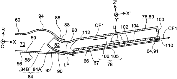
1. A convergent-divergent flap pair for a turbojet engine nozzle of a variable-geometry convergent-divergent type, comprising a convergent flap, and a divergent flap mounted pivotably on the convergent flap about a pivot axis, whereby the convergent-divergent flap pair is capable of going from a first extreme angular configuration, in which the convergent flap and the divergent flap make between them a maximum salient angle, to a second extreme angular configuration, in which the convergent flap and the divergent flap make between them a minimum salient angle smaller than the maximum salient angle,
wherein the convergent flap includes a respective inner wall, having a respective inner surface for channelling combustion gas and a respective outer surface, and a respective outer wall,
wherein the convergent flap includes a respective duct for circulation of cooling air defined between the respective outer surface of the respective inner wall of the convergent flap, and the respective outer wall of the convergent flap,
wherein the divergent flap includes a respective inner wall, having a respective inner surface for channelling the combustion gas and a respective outer surface, and a respective outer wall,
wherein the divergent flap includes a respective duct for circulation of cooling air defined between the respective outer surface of the respective inner wall of the divergent flap, and the respective outer wall of the divergent flap, and connected to the respective duct for circulation of the cooling air of the convergent flap,
wherein the divergent flap further includes a multiperforated plate provided with impingement cooling orifices, and extending between the respective inner wall and the respective outer wall of the divergent flap, whereby the multiperforated plate divides the respective duct for circulation of the cooling air of the divergent flap into:
a cavity for circulation of cooling air, defined between the respective outer wall of the divergent flap and the multiperforated plate, and connected to the respective duct for circulation of cooling air of the convergent flap, and
an impingement cooling cavity defined between the multiperforated plate and the respective outer surface of the respective inner wall of the divergent flap, to allow a cooling of the respective inner wall of the divergent flap by impingement of jets of air formed through the impingement cooling orifices from air circulating in the cavity for circulation of the cooling air,
wherein the divergent flap includes two opposite respective lateral end walls each connecting the respective inner wall of the divergent flap to the respective outer wall of the divergent flap, so that each of the cavity for circulation of cooling air and the impingement cooling cavity is further defined by the two respective lateral end walls of the divergent flap,
wherein each of the two respective lateral end walls of the divergent flap is provided with air passage orifices through which the impingement cooling cavity opens towards an outside.
|