| CPC A61M 39/1011 (2013.01) [A61M 39/24 (2013.01); A61M 2039/2426 (2013.01)] | 18 Claims |

|
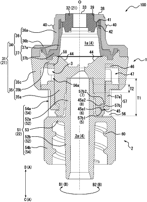
1. A medical connector comprising:
a first connection section that defines a first passage;
a second connection section that defines a second passage communicating with the first passage; and
a rotation control section that controls relative rotation of the first connection section and the second connection section in a connection state;
wherein the second connection section comprises a first wall face configured to abut on the first connection section to restrict the first connection section from moving in a direction to be separated from the second connection section along an axis of the first passage and the second passage;
wherein, in a state in which the first wall face abuts on the first connection section, the rotation control section allows the second connection section to rotate relative to the first connection section in a first circumferential direction about the axis and restricts the second connection section from rotating relative to the first connection section in a second circumferential direction opposite to the first circumferential direction;
wherein the first connection section is connectable to a first medical device using a rotating operation in the second circumferential direction and is disconnectable from the first medical device using a rotating operation in the first circumferential direction;
wherein the first connection section comprises:
a first tubular portion,
an annular groove formed in an outer surface of the first tubular portion,
a support portion that extends outward from the first tubular portion, and
an outer tubular portion extending from the support portion;
wherein the second connection section comprises:
a second tubular portion inserted into the first tubular portion, and
a claw portion that is located outward of the first tubular portion in a radial direction and fits into the annular groove, wherein the claw portion comprises the first wall face; and
wherein the outer tubular portion of the first connection section extends distally from the support portion such that part of the claw portion is located between the first tubular portion and the outer tubular portion in the radial direction.
|