| CPC A45D 29/02 (2013.01) [A45D 2029/026 (2013.01)] | 3 Claims |

|
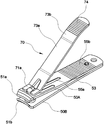
1. A nail clipper comprising:
a body comprising an upper elastic plate (50A) and a lower plate (50B) respectively having cutting blades (51a and 51b) in front ends thereof and holes (52a and 52b) in positions adjacent to the cutting blades, wherein the upper elastic plate and the lower plate are arranged in a top-bottom direction, and the cutting blades face each other while being spread from each other;
a lever (70) comprising a supporting portion (71a) having a coupling hole (72); and
a support pin (60) fitted into the holes (52a and 52b) of the upper elastic plate and the lower plate, with a catching protrusion (61) thereof being fitted to the coupling hole (72) of the lever (70), thereby coupling the body and the lever,
wherein, in a section (S3) opposite to the cutting blades (51a and 51b) of the upper elastic plate (50A) and the lower plate (50B), a portion of the upper elastic plate is stacked on a portion of the lower plate, and a concave portion (53) is provided in a bottom surface of the upper elastic plate in a position forward of the section (S3) and the concave portion (53) forms a thickness-reduced portion (54) in the upper elastic plate (50A),
when the cutting blade (51a) of the upper elastic plate (50A) and the cutting blade (51b) of the lower plate (50B) are brought into engagement with each other, the cutting blade of the upper elastic plate is located rearward of the cutting blade of the lower plate with a distance (x), and
a stepped portion (58a, 58b) is provided in an inner portion of an inclined portion (57a, 57b) of the front end of each of the upper elastic plate (50A) and the lower plate (50B) wherein a slot (55a) is provided on one side of a surface of the upper elastic plate, and fine grooves (55b) are provided on an opposite side of the surface of the upper elastic plate,
wherein an angle (b, c) of the cutting blade (51a, 51b) formed in the inclined portion (57a, 57b) of each of the upper elastic plate (50A) and the lower plate (50B) ranges from 28° to 32°, and when the cutting blades are brought into engagement with each other, the distance (x) between the cutting blades ranges from 0.03 mm to 0.07 mm.
|