| CPC H05K 1/0215 (2013.01) [H01G 2/08 (2013.01); H01G 2/106 (2013.01); H05K 7/2039 (2013.01); H05K 2201/10409 (2013.01)] | 2 Claims |

|
1. An electrical device, comprising:
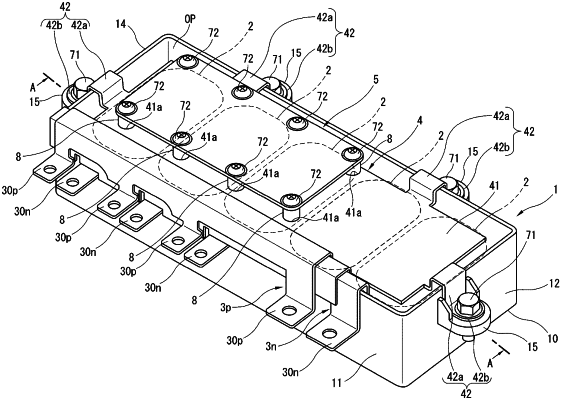
a case formed in a rectangular parallelepiped shape with base sides thereof having a largest area, a first base side of the base sides being open to define an opening portion, a second base side of the base sides being closed by a bottom wall; and
a capacitor installed in the case,
wherein the electrical device further comprises:
a heat sink plate made of a first metal material and disposed on the opening portion of the case such that an inner surface of the heat sink plate faces the capacitor;
a fastening part adapted for fastening to a screw and provided on an outer surface of the heat sink plate opposite from the capacitor, the fastening part comprising a nut made of a second metal material; and
a circuit board attached by the screw fastening to the fastening part,
wherein the heat sink plate is electrically connected to a metallic frame by which the electrical device is fixed,
wherein the circuit board has:
a circuit pattern provided on a pattern surface of the circuit board opposed to the outer surface of the heat sink plate, the pattern surface on which the circuit pattern is provided facing the capacitor with the heat sink plate interposed between the pattern surface and the capacitor;
a screw through hole formed through the pattern surface so as to allow insertion therethrough of the screw fastened to the nut; and
a pattern for grounding the circuit pattern, provided at a hole edge of the screw through hole on the pattern surface of the circuit board, and
wherein an area of the outer surface of the heat sink plate oriented along the opening portion of the case is larger than an area of the pattern surface of the circuit board oriented along the opening portion of the case.
|