US 12,068,744 B2
Trigger assembly
John S. Dey, IV, New York, NY (US); and Jacob P. Schneider, Cedarburg, WI (US)
Assigned to MILWAUKEE ELECTRIC TOOL CORPORATION, Brookfield, WI (US)
Filed by MILWAUKEE ELECTRIC TOOL CORPORATION, Brookfield, WI (US)
Filed on May 2, 2023, as Appl. No. 18/142,294.
Application 18/142,294 is a continuation of application No. 16/660,310, filed on Oct. 22, 2019, granted, now 11,677,397.
Application 16/660,310 is a continuation of application No. 15/714,220, filed on Sep. 25, 2017, granted, now 10,491,211, issued on Nov. 26, 2019.
Claims priority of provisional application 62/400,707, filed on Sep. 28, 2016.
Prior Publication US 2023/0275582 A1, Aug. 31, 2023
This patent is subject to a terminal disclaimer.
Int. Cl. H03K 17/965 (2006.01); G01D 5/20 (2006.01); H01F 5/00 (2006.01); H02K 11/28 (2016.01); H03K 17/96 (2006.01); H03K 17/97 (2006.01)
CPC H03K 17/9618 (2013.01) [G01D 5/202 (2013.01); H01F 5/003 (2013.01); H02K 11/28 (2016.01); H03K 17/97 (2013.01); H03K 2017/9706 (2013.01)] 20 Claims
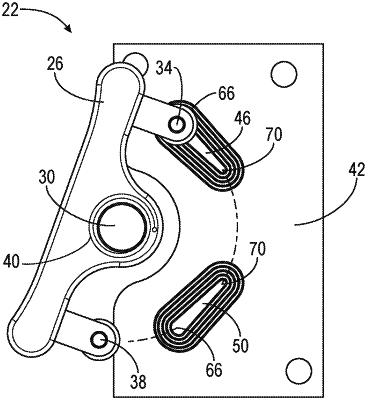
OG exemplary drawing
 
1. A trigger assembly for use with a power tool having an electric motor, the trigger assembly comprising:
a trigger;
a conductor coupled for movement with the trigger; and
a printed circuit board having an inductive sensor thereon responsive to relative movement between the conductor and the inductive sensor caused by movement of the trigger,
wherein an output of the inductive sensor is used to activate the electric motor,
wherein the conductor moves between a first position and a second position, and
wherein the first position is outside the detection area of the inductive sensor and the second position is within the detection area of the inductive sensor.