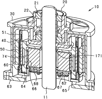
| CPC H02K 9/223 (2021.01) [H02K 3/50 (2013.01); H02K 21/14 (2013.01); H02K 2203/06 (2013.01)] | 21 Claims |

|
1. A rotating electrical machine comprising:
a magnetic field generator that comprises a magnet unit, the magnet unit including a plurality of magnetic poles arranged to have magnetic polarities that alternate in a circumferential direction of the rotating electrical machine;
an armature that comprises a hollow cylindrical core and a multi-phase armature coil having opposing first and second ends in an axial direction of the rotating electrical machine, one of the magnetic field generator and the armature serving as a rotor,
the armature coil including:
a side portion that radially faces the magnet unit and comprises coil parts for each phase; and
a pair of first and second end portions disposed at the respective first end and second end, each of the first and second end portions electrically connecting the coil parts of the side portion for each phase to constitute a circuit for the corresponding phase; and
a holder member located as an independent member from the armature, with the hollow cylindrical core of the armature between the holder member and the magnetic field generator so that the holder member is disposed to be radially closer to the armature coil than to the magnetic field generator, the holder member being configured to hold the armature coil, the holder member having:
a first portion that faces the first end portion of the armature coil; and
a second portion that faces the second end portion of the armature coil, the first portion of the holder member being thermally coupled to an inner peripheral side of the first end portion of the armature coil, the second portion of the holder member being thermally coupled to an inner peripheral side of the second end portion of the armature coil.
|