| CPC H02J 3/06 (2013.01) [H01H 3/28 (2013.01); H02J 9/06 (2013.01); H01H 2300/018 (2013.01); H02J 9/068 (2020.01)] | 20 Claims |

|
1. A method comprising:
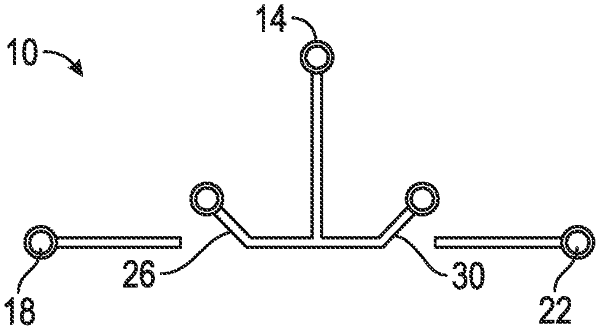
coupling a first source pole of a first reverse flow automatic transfer switch with a first power source;
coupling a first load pole of the reverse flow automatic transfer switch with a first load;
coupling a second load pole of the reverse flow automatic transfer switch with a second load;
selectively closing a first switch of the reverse flow automatic transfer switch to couple the first load pole to the source pole;
selectively closing a second switch of the reverse flow automatic transfer switch to couple the second load pole to the source pole;
coupling a second source pole of a second reverse flow automatic transfer switch with a second power source;
selectively coupling a third load pole with the second load pole of the first reverse flow automatic transfer switch and the second load; and
selectively coupling a fourth load pole to the first load pole of the first reverse flow automatic transfer switch and the first load to provide a ring bus topology.
|