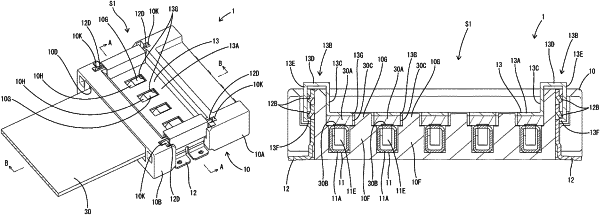
| CPC H01R 13/635 (2013.01) | 7 Claims |

|
1. A connector, comprising:
a connector housing including a board accommodation space;
a terminal fitting mounted in the connector housing to face the board accommodation space; and
a retainer for sandwiching and holding a flexible printed circuit arranged in the board accommodation space between the terminal fitting and the retainer,
wherein:
a state of the retainer changes to a pressing state for pressing the flexible printed circuit toward the terminal fitting and a non-pressing state for releasing pressing to the flexible board,
the retainer is made of metal,
a peg positioned on a side surface of the connector housing and including a vertical flat plate and a lower end part bent horizontally from the flat plate for mounting the connector housing on a board, the flat plate including a plurality of upper and lower locked portions cut and raised laterally outward,
the retainer includes an outer wall portion for covering the peg from outside, and
the outer wall portion is provided with a locking body extending inward from a lower end of the outer wall portion toward the peg and to be locked to the lower locked portion.
|