| CPC H01M 50/367 (2021.01) [H01M 10/613 (2015.04); H01M 10/653 (2015.04); H01M 50/209 (2021.01); H01M 50/271 (2021.01); H01M 50/264 (2021.01); H01M 50/293 (2021.01); H01M 2220/20 (2013.01)] | 8 Claims |

|
1. A battery module comprising:
a battery stack including a plurality of batteries that are stacked, the plurality of batteries including valves through which a gas is blown off, the valves being disposed on a first surface of the battery stack;
a duct plate configured to cover the first surface of the battery stack, the duct plate including a gas discharge duct that extends in a stacking direction of the batteries, is connected to the valves of the batteries, and temporarily stores the gas blown off through the valves;
a cover plate placed on the duct plate;
a flow path defined by the duct plate and the cover plate, the flow path being connected to the gas discharge duct through a plurality of openings arranged in the stacking direction of the batteries, the flow path extending from the gas discharge duct in a first direction that intersects with the stacking direction of the batteries, the flow path allowing leaking of the gas in the gas discharge duct to an outside of the battery module; and
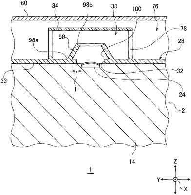
a plurality of gas restricting walls each disposed in the gas discharge duct and between a valve of the valves and at least an opening of the plurality of openings closest to the valve, each of the plurality of gas restricting walls extending in a direction that intersects with the first surface,
wherein each of the plurality of gas restricting walls has one end thereof directly connected with the duct plate, and another end thereof spaced apart from an inner surface of the gas discharge duct in a second direction along which the duct plate and the cover plate are arranged.
|