| CPC H01F 27/2804 (2013.01) [H01F 27/24 (2013.01); H01F 27/29 (2013.01); H01F 2027/2809 (2013.01)] | 12 Claims |

|
1. A coil component comprising:
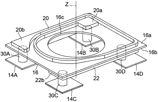
an elementary body having a mounting surface corresponding to a mounting substrate;
a first pair of external terminal electrodes and a second pair of external terminal electrodes provided on the mounting surface;
an insulating substrate provided in the elementary body, the insulating substrate extending parallel to the mounting surface;
a first planar coil provided on a first main surface of the insulating substrate on a side further from the mounting surface, the first planar coil having a single-layer structure, an inner end portion located on an inner peripheral side of the first planar coil, and an outer end portion located on an outer peripheral side of the first planar coil;
a second planar coil provided on a second main surface of the insulating substrate on a side closer to the mounting surface and wound around the same magnetic core as a magnetic core of the first planar coil, the second planar coil having a single-layer structure, an inner end portion located on an inner peripheral side of the second planar coil, and an outer end portion located on an outer peripheral side of the second planar coil;
a first pair of connecting conductors extending inside the insulating substrate and the elementary body in a direction orthogonal to the mounting surface and respectively connecting the inner end portion and the outer end portion of the first planar coil to the first pair of external terminal electrodes, each of the first pair of connecting conductors, as a whole, extending in the direction orthogonal to the mounting surface without having a layer that is parallel to the mounting surface, the first pair of connecting conductors including a first inner connecting conductor and a first outer connecting conductor, the first pair of external terminal electrodes including a first inner external terminal electrode and a first outer external terminal electrode, the first inner connecting conductor connecting the inner end portion of the first planar coil to the first inner external terminal electrode, the first outer connecting conductor connecting the outer end portion of the first planar coil to the first outer external terminal electrode; and
a second pair of connecting conductors extending inside the elementary body in the direction orthogonal to the mounting surface and respectively connecting the inner end portion and the outer end portion of the second planar coil to the second pair of external terminal electrodes, each of the second pair of connecting conductors, as a whole, extending in the direction orthogonal to the mounting surface without having a layer that is parallel to the mounting surface, the second pair of connecting conductors including a second inner connecting conductor and a second outer connecting conductor, the second pair of external terminal electrodes including a second inner external terminal electrode and a second outer external terminal electrode, the second inner connecting conductor connecting the inner end portion of the second planar coil to the second inner external terminal electrode, the second outer connecting conductor connecting the outer end portion of the second planar coil to the second outer external terminal electrode,
wherein the elementary body includes a magnetic body covering the first main surface of the insulating substrate along with the first planar coil provided thereon and the second main surface of the insulating substrate along with the second planar coil provided thereon,
wherein, when viewed in the direction perpendicular to the mounting surface, one of the first pair of connecting conductors connected to the inner end portion of the first planar coil is located inside the second planar coil and one of the second pair of connecting conductors connected to the inner end portion of the second planar coil is located inside the first planar coil,
wherein the insulating substrate is provided with a pair of through holes through which the first pair of connecting conductors penetrate, and
wherein, when viewed in the direction perpendicular to the mounting surface, the inner end portion of the first planar coil and the first inner external terminal electrode overlap and form a first overlapping region, the inner end portion of the second planar coil and the second inner external terminal electrode overlap and form a second overlapping region, the first inner connecting conductor is located in the first overlapping region, and the second inner connecting conductor is located in the second overlapping region.
|