| CPC G11B 20/10009 (2013.01) [G11B 5/09 (2013.01); G11B 20/24 (2013.01)] | 20 Claims |

|
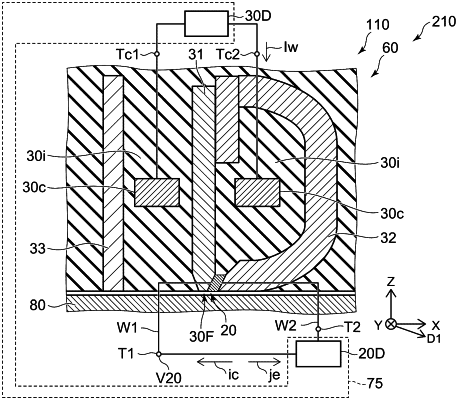
1. A magnetic recording device, comprising:
a magnetic head including
a first magnetic pole,
a second magnetic pole,
a magnetic element provided between the first magnetic pole and the second magnetic pole,
a first terminal electrically connected to the first magnetic pole,
a second terminal electrically connected to the second magnetic pole, and
a coil; and
a controller electrically connected to the first terminal, the second terminal, and the coil,
an end of the magnetic element being electrically connected to the first magnetic pole,
another end of the magnetic element being electrically connected to the second magnetic pole,
the controller being configured to perform a recording operation,
in the recording operation, the controller being configured to supply a recording current to the coil while applying an element voltage not less than a first voltage and not more than a second voltage between the first terminal and the second terminal,
when the element voltage, the first voltage and the second voltage being applied, a second potential of the second magnetic pole being lower than a first potential of the first magnetic pole,
a differential resistance of the magnetic element when a positive applied voltage applied between the first terminal and the second terminal being changed while the recording current being supplied to the coil becoming a first peak when the applied voltage being the first voltage,
when the positive applied voltage being applied, the second potential being lower than the first potential,
when a first applied voltage being applied between the first terminal and the second terminal while the recording current being supplied to the coil, a first signal being generated between the first terminal and the second terminal,
the first signal having a first intensity when the first applied voltage being a first value of positive,
the first signal having a second intensity when the first applied voltage being a second value of negative,
a ratio of an absolute value of a difference between the first intensity and the second intensity to a normalized change rate being not less than 1 at the second voltage,
an absolute value of the second value being same as the first value,
when the first applied voltage being positive, the second potential being lower than the first potential,
when the first applied voltage being negative, the second potential being higher than the first potential, and
the normalized change rate being a product of the first voltage and an absolute value of the change rate of the second intensity with respect to the first applied voltage when the first applied voltage being negative.
|