| CPC G03B 7/00 (2013.01) [G01D 5/14 (2013.01)] | 18 Claims |

|
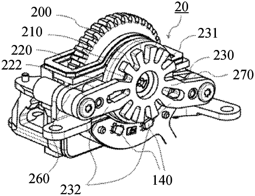
1. A rotatable operation apparatus comprising:
a rotatable operation member configured to be rotatable about a predetermined axis;
a base member configured to rotatably support the rotatable operation member;
a magnet in which a plurality of magnetic poles are alternately magnetized and a magnetized direction of each of the plurality of magnetic poles is parallel to the predetermined axis, wherein the magnet has a ring shape and is configured to rotate about the predetermined axis as the rotatable operation member rotates;
first and second magnetic members arranged so that each of the first and second magnetic members faces a magnetized surface of the magnet and that the magnet is disposed between the first and second magnetic members;
a body frame configured to hold the base member; and
a detector configured to detect a change in a magnetic field caused by a rotation of the magnet,
wherein the first magnetic member includes a first tooth and the second magnetic member includes a second tooth,
wherein the rotatable operation apparatus is capable of generating an operation force according to a change in positions of the plurality of magnetic poles relative to positions of the first tooth and the second tooth, where the change in the positions is caused by the rotation of the magnet,
wherein the magnet, the first magnetic member, and the second magnetic member are housed inside the body frame,
wherein, in a view from a thrust direction of the magnet, the detector is disposed at a position that does not overlap with the magnet,
wherein the detector includes a first magnetic field detector and a second magnetic field detector, and
wherein the first magnetic field detector and the second magnetic field detector are configured to detect the magnetic field in a circumferential direction of the magnet and the magnetic field in the thrust direction of the magnet.
|