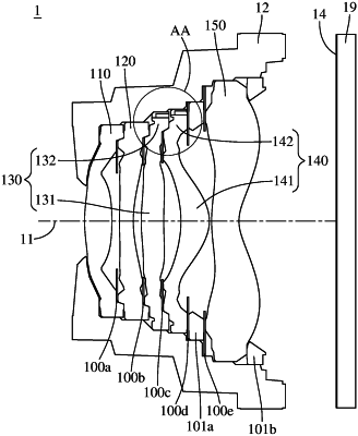
| CPC G02B 7/021 (2013.01) [G02B 3/04 (2013.01); G03B 9/54 (2013.01)] | 19 Claims |

|
1. An imaging lens system, having an optical axis, and the imaging lens system comprising:
at least one optical element, wherein the at least one optical element comprises, in order from a center to a periphery thereof:
a central portion, wherein the optical axis passes through the central portion, the central portion comprises a central opening structure, the central opening structure has a first tapered surface and a second tapered surface that surround the central portion, the first tapered surface faces an object side and is tapered off towards an image side, the second tapered surface faces the image side and is tapered off towards the object side, and the first tapered surface and the second tapered surface are connected to form a central opening; and
an outer ring portion, wherein the outer ring portion surrounds the central portion, and the outer ring portion comprises, on at least one of an object side and an image side thereof:
at least one annular groove structure, wherein the at least one annular groove structure is in a full-circle form, and the at least one annular groove structure is tapered off from the object side to the image side of the outer ring portion or from the image side to the object side of the outer ring portion;
at least one flat abutting portion, wherein the at least one flat abutting portion is located closer to the central portion than the at least one annular groove structure, and the at least one flat abutting portion is in physical contact with another optical element which is adjacent to the at least one optical element of the imaging lens system; and
at least one full-circle connecting portion, wherein the at least one full-circle connecting portion is connected to the at least one annular groove structure, the at least one full-circle connecting portion is located farther away from the central portion than the at least one annular groove structure, and the at least one full-circle connecting portion is exposed to air and is not in physical contact with the optical element and another optical element adjacent thereto;
wherein the at least one annular groove structure has:
an annular bottom end surface, extending in a direction substantially perpendicular to the optical axis;
a first annular side wall, wherein the first annular side wall is connected to the annular bottom end surface and the at least one full-circle connecting portion, and the first annular side wall extends in a direction away from the annular bottom end surface; and
a second annular side wall, wherein the second annular side wall is connected to the annular bottom end surface, the second annular side wall is located closer to the central portion than the annular bottom end surface, and the second annular side wall extends in a direction away from the annular bottom end surface;
wherein a minimum diameter of the first annular side wall is ΦA1, a maximum diameter of the second annular side wall is ΦA2, a length of the annular bottom end surface in a direction perpendicular to the optical axis is (ΦA1−ΦA2)/2, and the following condition is satisfied:
0.005 [mm]≤(ΦA1−A2)/2<0.2 [mm].
|