| CPC G01R 31/31727 (2013.01) [H03H 7/06 (2013.01); H03K 19/21 (2013.01); H03K 3/037 (2013.01)] | 21 Claims |

|
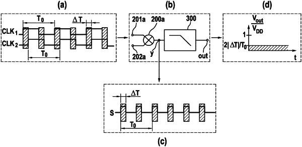
1. A method for measuring a phase shift between a first clock signal and a second clock signal, the first clock signal and the second clock signal having the same frequency, the method comprising the following steps:
a-1) feeding the first clock signal into a first input of a mixer;
a-2) feeding the second clock signal into a second input of the mixer, wherein the mixer includes an XOR gate that has a first input controlled using the first clock signal and a second input controlled using the second clock signal;
d) feeding an output signal of the mixer into a low pass filter; and
e) measuring the output signal of the low pass filter;
wherein the method includes at least one of the following two features (I)-(II);
(I) the method further comprises the step of f) normalizing the output signal of the low pass filter to a period duration of the first and second clock signals and an operating voltage of the mixer, wherein the normalization includes:
(i) the output signal of the low pass filter being multiplied by one-half the period duration and divided by the operating voltage of the mixer; or
(ii) a difference between the operating voltage of the mixer and the output signal of the low pass filter being multiplied by the period duration and divided by the operating voltage of the mixer; and
(II) (i) the mixer includes a first edge-controlled flip-flop, a second edge-controlled flip-flop, and an AND gate (ii) step a-1) includes feeding the first clock signal into a dynamic input of the first flip-flop, (iii) step a-2) includes feeding the second clock signal into a dynamic input of the second flip-flop, and (iv) the method further comprises the steps of:
b-1) feeding an output signal of the first flip-flop into a first input of the XOR gate and into a first input of the AND gate;
b-2) feeding an output signal of the second flip-flop into a second input of the XOR gate and into a second input of the AND gate;
c-1) relaying an output signal of the AND gate to a reset input of the first flip-flop; and
c-2) relaying the output signal of the AND gate to a reset input of the second flip-flop.
|