| CPC F25B 13/00 (2013.01) [F25B 40/02 (2013.01); F25B 2313/006 (2013.01); F25B 2313/009 (2013.01); F25B 2313/0233 (2013.01); F25B 2313/0252 (2013.01); F25B 2400/13 (2013.01); F25B 2600/2509 (2013.01)] | 12 Claims |

|
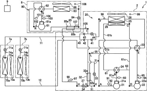
1. A refrigeration cycle device comprising:
a main refrigerant circuit having
a main compressor that compresses a main refrigerant,
a main heat-source-side heat exchanger that selectively functions as a radiator and an evaporator of the main refrigerant,
a main usage-side heat exchanger that selectively functions as an evaporator and a radiator of the main refrigerant,
an injection pipe that causes the main refrigerant that flows between the main heat-source-side heat exchanger and the main usage-side heat exchanger to branch off and to be sent to the main compressor,
an economizer heat exchanger that cools the main refrigerant that flows between the main heat-source-side heat exchanger and the main usage-side heat exchanger by heat exchange with the main refrigerant that flows in the injection pipe, and
a main flow-path switching mechanism that switches between a main cooling operation state, in which the main refrigerant is caused to circulate so that the main usage-side heat exchanger functions as the evaporator of the main refrigerant, and a main heating operation state, in which the main refrigerant is caused to circulate so that the main usage-side heat exchanger functions as the radiator of the main refrigerant,
wherein the main refrigerant circuit has a sub-usage-side heat exchanger that selectively functions as a cooler and a heater of the main refrigerant that has been cooled at the economizer heat exchanger; and
a sub-refrigerant circuit having
a sub-compressor that compresses a sub-refrigerant,
a sub-heat-source-side heat exchanger that selectively functions as a radiator and an evaporator of the sub-refrigerant,
the sub-usage-side heat exchanger that selectively functions as an evaporator of the sub-refrigerant and cools the main refrigerant that has been cooled at the economizer heat exchanger, and selectively functions as a radiator of the sub-refrigerant and heats the main refrigerant that has been cooled at the economizer heat exchanger, and
a sub-flow-path switching mechanism that switches between a sub-cooling operation state, in which the sub-refrigerant is caused to circulate so that the sub-usage-side heat exchanger functions as the evaporator of the sub-refrigerant, and a sub-heating operation state, in which the sub-refrigerant is caused to circulate so that the sub-usage-side heat exchanger functions as the radiator of the sub-refrigerant,
wherein
the main refrigerant flows in the order of the main compressor, the main heat-source-side heat exchanger, the economizer heat exchanger, the sub-usage-side heat exchanger and the main usage-side heat exchanger during the main cooling operation state.
|