| CPC F24H 9/2085 (2013.01) [F23D 14/04 (2013.01); F23L 17/005 (2013.01); F23L 17/16 (2013.01); F24H 3/006 (2013.01); F24H 15/242 (2022.01); F24H 15/254 (2022.01); F24H 15/281 (2022.01); F24H 15/31 (2022.01); F24H 15/35 (2022.01); F24H 15/36 (2022.01); F24H 15/414 (2022.01); F24H 15/464 (2022.01)] | 19 Claims |

|
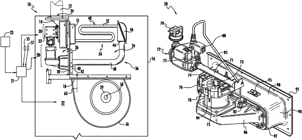
1. A fuel-fired heating appliance, comprising:
a fuel source comprising gas valves, the gas valves comprising a main gas valve, a pilot gas valve, and a solenoid valve;
an air source;
a chamber in which fuel from the fuel source and air from the air source mix, thereby forming a fuel-air mixture having an air/fuel ratio;
a burner downstream from the chamber configured to receive a flow of the fuel-air mixture;
a heat exchanger in fluid communication at an input end thereof with an area proximate the burner;
a blower in fluid communication with an output of the heat exchanger so that actuation of the blower draws combustion gas from the burner, through the heat exchanger, and to the blower;
a controller in operative communication with the blower and with a thermostat;
an igniter in operative communication with the controller and disposed in the chamber, the igniter configured to create a spark;
a flame sensor disposed in the chamber that is configured to detect a flame and send a corresponding signal to the controller; and
a computer readable medium containing program instructions executable by the controller to:
provide a control signal to the blower to operate at a purge period speed for a purge period, wherein the main gas valve is closed during the purge period;
following the purge period, provide a control signal to the blower to operate at an initial target speed calibrated to draw air to the burner at a flow rate that is lower than an air flow drawn by the blower at a steady-state speed and is lower than the purge period speed;
in response to receiving a signal from the thermostat requesting activation of the fuel-fired heating appliance, while the blower is at the initial target speed, activate a pilot flame by opening the pilot valve and the solenoid valve, and sending a signal to the igniter;
in response to receiving a signal from the flame sensor that a flame is present, open the main gas valve, close the solenoid valve, and provide a control signal to the blower to increase blower speed to at least one incremental speed that is faster than the initial target speed but slower than a steady-state speed; and
provide a control signal to the blower to increase blower speed to the steady-state speed after operation of the blower at the at least one incremental speed.
|