| CPC F21S 41/265 (2018.01) [F21S 41/143 (2018.01); F21S 41/151 (2018.01); F21S 45/47 (2018.01); F21V 5/008 (2013.01)] | 8 Claims |

|
1. A vehicle lamp comprising:
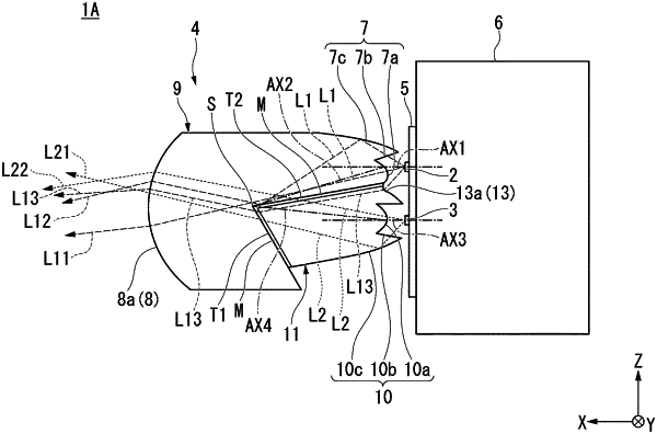
a first light source configured to emit first light;
a second light source that is disposed adjacent to the first light source and that is configured to emit second light in a same direction as the first light; and
a projection lens configured to project the first light and the second light in the same direction,
wherein the projection lens has a first lens body including a first incidence part located in an area facing the first light source and an emission part located on a side opposite to the first incidence part, and a second lens body including a second incidence part located in an area facing the second light source and a third incidence part between the first incidence part and the second incidence part, and
a structure in which the first lens body and the second lens body abut against each other in a state in which first boundary surfaces and second boundary surfaces are interposed between the first lens body and the second lens body, the first boundary surfaces being provided between the first lens body and the second lens body at between the emission part and the third incidence part, and second boundary surfaces being provided between the first lens body and the second lens body and extending from a boundary line with respect to the first boundary surface until the first incidence part and the third incidence part,
the first boundary surfaces and the second boundary surfaces are disposed at an acute angle while having the boundary line disposed therebetween,
among first light entering an inside of the first lens body from the first incidence part, first light reflected at the second boundary surface is emitted to outside of the first lens body from the emission part,
among second light entering an inside of the second lens body from the second incidence part, second light passing through the first boundary surface and second light passing through the second boundary surface are emitted to the outside of the first lens body from the emission part, and
among first light entering the inside of the second lens body from the third incidence part, first light passing through the first boundary surface is emitted to the outside of the first lens body from the emission part.
|