| CPC F03B 3/12 (2013.01) [F03B 13/10 (2013.01); F03B 17/00 (2013.01); F03B 17/04 (2013.01); Y02E 10/20 (2013.01)] | 15 Claims |

|
1. A method for operating a turbine engine and enhancing its power output by harnessing fluid pressure, the method comprises:
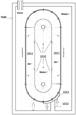
providing a container (1030) filled with a fluid and having a rotor (1011) mounted within, where the rotor includes at least one shaft and bearing to facilitate its rotation and is designed to allow for the adjustment of its internal space height to influence the dynamic moment of objects (1014) arranged within, the rotor's internal space includes springs, support frames, or support rods;
integrating a support-guideway system within the container to guide the motion pattern of the rotor based on the system's configuration;
arranging a plurality of objects (1014) within the rotor, these objects configured to move in response to fluid pressure changes within the container, thereby contributing to the dynamic torque within the rotor;
affixing a shielding device (1012) atop a bracket (1013) that is securely attached to the container, with the shielding device positioned on one side of the radial axis (1010) and in intimate contact with a surface of the rotor (1011), this configuration is engineered to block upward buoyant force at this location, creating zones of differential buoyancy within the rotor's operational environment, while the rotor (1011) on the opposite side experiences upward buoyancy;
configuring the rotor to rotate in response to the differential in fluid pressure acting on the objects, with such differential resulting from the transition of the objects between buoyant and non-buoyant regions;
extracting rotational energy from the shaft (1010) connected to the rotor, propelled by the movement of the objects within the rotor due to the differential fluid pressure; and
enhancing the turbine engine's power output by optimizing the distribution and movement of the objects within the rotor to maximize the pressure differential and resultant rotational force.
|