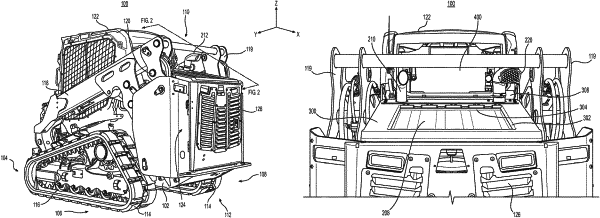
| CPC F02M 35/10013 (2013.01) [E02F 9/0866 (2013.01); E02F 9/163 (2013.01); F01N 13/002 (2013.01); F02M 35/164 (2013.01); F01N 2340/04 (2013.01); F01N 2590/08 (2013.01)] | 20 Claims |

|
1. A machine, comprising:
a frame;
an engine compartment located in a rear section of the frame with respect to a direction of forward travel for the machine, the engine compartment comprising a top outer surface, a side outer surface, and a rear outer surface of the machine;
an internal combustion engine mounted within the engine compartment;
a cooling vent within the top outer surface, the cooling vent being configured to eject heated air upwardly from the engine compartment into atmosphere;
a boundary on the top outer surface of the engine compartment separating the cooling vent from a remainder of the top outer surface;
an intake pipe at least partially within the engine compartment configured to pass ambient air from a distal end of the intake pipe into the engine; and
a directional intake cap having sides enclosing an elongated cavity between an inlet opening and an outlet opening, the inlet opening being configured to take in the ambient air for the engine, the outlet opening being coupled to the distal end of the intake pipe, wherein the directional intake cap is rotationally oriented on the intake pipe in a position in the rear section of the frame such that:
with respect to a longitudinal axis of the machine, the inlet opening is vertically over at least a portion of the top outer surface of the engine compartment and laterally aside the cooling vent between a portion of the boundary and the side outer surface of the engine compartment, and
at least one of the sides of the directional intake cap is between the elongated cavity and the heated air ejected upwardly by the cooling vent.
|