| CPC F01D 5/187 (2013.01) [F01D 5/141 (2013.01); F01D 5/20 (2013.01); F01D 5/3007 (2013.01); F05D 2220/323 (2013.01); F05D 2240/307 (2013.01); F05D 2260/201 (2013.01); F05D 2260/202 (2013.01); F05D 2260/205 (2013.01)] | 16 Claims |

|
1. An airfoil comprising:
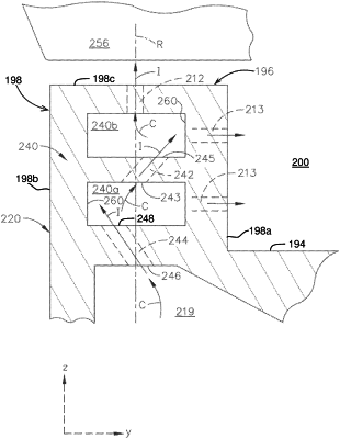
a body defining an interior having a cooling passage formed therein, the body extending axially between a leading edge and a trailing edge to define a chord-wise direction and radially between a root and a tip to define a span-wise direction, wherein the tip includes a tip end wall and a tip rail extending from the tip end wall and wherein the span-wise direction terminates in a distal end of the tip rail, the tip rail having:
an exterior surface extending between at least a first surface, a second surface, and a third surface interconnecting the first surface and the second surface, the third surface defining the distal end of the tip rail in the span-wise direction;
a first cooling cavity and a second cooling cavity spaced from each other within the tip rail with respect to the exterior surface of the tip rail;
a cooling conduit fluidly coupling the cooling passage with the first cooling cavity;
a connecting conduit fluidly coupling the first cooling cavity to the second cooling cavity; and
a first film hole extending between the second cooling cavity and the third surface and a second film hole extending between either the first cooling cavity or the second cooling cavity and the first surface;
wherein at least one of the connecting conduit or the cooling conduit is angled with respect to a radial axis of the body extending in the span-wise direction between the cooling passage and the third surface, the radial axis intersecting either one of the connecting conduit or the cooling conduit, respectively, at an angle.
|